This thread has been locked.

If you have a related question, please click the "Ask a related question" button in the top right corner. The newly created question will be automatically linked to this question.

UCC24636: DCDC CONVERTER, FLYBACK, 80-160V IN, 120V OUT, 1A, WEBENCH

Part Number: UCC24636
Other Parts Discussed in Thread: UCC28740, TL431

Dear officer,

I am writing to ask one question about a UCC24636 application in a flyback convert. 
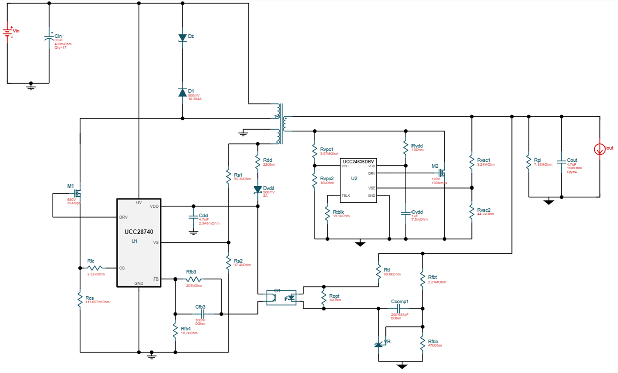
When I plug in 80-160VDC in, 120V 1A out into WEBENCH, it provides me this circuit.

Basically, it is a flyback converter. Transformer turns ratios are as below:

Primary : secondary = 15 : 20,

Aux : Secondary = 4 : 20.

However, I have noticed that it suggested using UCC24636 in the secondary and a 100V MOSFET M2 with it.

My question is 

1. VDD of UCC24636 has a max rating of 30V according to datasheet. Can we really use it here?

2. Can we use MOSFET M2 here since it has only 100V =  VDS-max. ? I think the max voltage across it would be Vout(120V) + Winding voltage (164V).

Can anyone help on this?

thanks,

JIM.

  • Hello Jim,


    Thank you for your interest in the UCC24636 SR controller (and UCC28740 flyback controller).


    You are correct; the UCC24636 cannot be directly powered from a 120V source.   Nor can the 100-V MOSFET, and also not the shunt regulator. I suspect that the Webench program contains some limitation(s) that does not properly accommodate higher voltage outputs. We’ll have to get that corrected.


    Meanwhile, the UCC24636 and the shunt regulator (probably TL431 or similar) can be locally biased by a suitable low voltage source. I suggest approximately 10-12 V for this source to provide sufficient gate drive to the SR Fet. It does not need to be very accurate, can provide bias to both SR controller and shunt regulator, and can be generated in several ways.


    The simplest method is a linear regulator using a high-voltage transistor (400-V rating, minimum) connected to Vout. A 12-V Zener can regulate the base of an NPN (lowest cost) or gate of a MOSFET (lowest standby current), while the emitter or source connects to VDD and the top of Rtl. A resistor from Vout to the Zener provides just enough current to obtain 12V, but the NPN will also need some base current at a non-saturated beta. The local bias voltage will be a diode drop or a Vgs_th down from the Zener voltage.


    Lower bias loss can be obtained at higher complexity by adding another secondary winding of 2-3 turns. A 2-turn secondary would reflect ~12V after rectification and filtering, but it would not be well regulated. However, it is likely to be sufficient for bias purposes. 3 turns would allow you to post-regulate it, if you find it necessary and worth the extra complexity and cost.


    The value of Rtl must be recalculated for the lower bias voltage.  I estimate (10V-2V) / ((120V-2V)/70K) = 4.7K.


    The SR MOSFET (which may see up to 120V + 160V/15*20 = 333V) does not need to be rated for 100A. Very roughly speaking, a 1-A average output will have ~4A peak at ~1.6A rms level at low line. A MOSFET of less than 200mR rating would provide less than 0.5W loss. Lower values of Rds(on) will have lower loss, of course, but too low will lead to diminishing returns and excess bias power loss at excess cost.


    Note: I also suggest to insert a damping resistor in series with the Main Fet (M1) gate in case pcb layout inductance results in some turn-on/turn-off oscillations.  A 0-R placeholder can be added, and the suitable value (usually 2-10R) selected as needed.


    Regards,

    Ulrich