This thread has been locked.

If you have a related question, please click the "Ask a related question" button in the top right corner. The newly created question will be automatically linked to this question.

LM5001: Peripheral parts when using LM5001

Part Number: LM5001

Dear all,

I would like to ask about LM5001

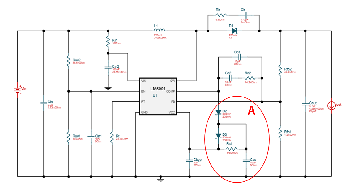
When comparing the circuit in the data sheet Figure 20 and the circuit in WEBENCH, in the circuit of WEBENCH, the part in the red circle is additionally attached to the circuit in the data sheet.
(I have a request from our customers to configure as few peripheral components as possible.)


① If the EN pin is not used, are the blue circled parts (Rcv1, Rcv2, Cin1) unnecessary?

 (If the EN pin is not used, is it okay to leave it open?)
②The description of Rb and Cb arranged in parallel with D1 could not be confirmed in the data sheet. Is it necessary to use the LM5001?

(If you don't mind, please tell me the roles of Rb and Cb.)

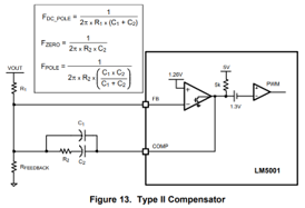
③Cc1 is not included in the data sheet Figure20. Does the following loop compensation work without Cc1?
(If C1 does not exist, I think that Cc1 is necessary because Fpole of the calculation in the following figure cannot be derived)

④ If it is not necessary to set the soft start, are the parts (D2, D3, Rs1, Css) in red circle A shown in the data sheet Figure.20 unnecessary?

 Also, if you need to set soft start, what kind of problem is there when you use only Css without D2, D3 and Rs1?

* By the way, customers are considering using under the following conditions.
Vin = 18V-30V
Vout = 40V
Iout = 0.25A

Best Regards,

Y.Ottey

  • Hi Y. Ottey,

    First, thank you for considering our product.

    Please understand that the datasheet has the fundamental circuit, and the Webench presents a real schematic with additional functions.  For instance the capacitor at the UVLO offers some noise filtering to prevent false triggering;  the circuit in circuit A implements the soft-start; Rb-Cb form the snubber to attenuate ringing during switching; and Cc1 adds a pole to the compensation, to complete it as the typical Type-2 compenstator for current mode controlled circuit. 

    To answer your questions:

    (1) yes, you can leave the EN pin floating, if you do not want to program the UVLO threshold.

    (2) It is a good practice to reserve the snubber position on PCB in case it is needed after testing.  You can choose not to install, but having the flexibility can save your develop time.

    (3) You will loose the pole.  You can still use the formula by setting Cc1=0 if you don;t want to have it. 

    (4) You are correct.  You can give up the soft-start by not using these parts.  However, I would recommend to you reserve the position on your PCB in case you need it later.  

    The LM5001 should support the application.

    Thanks,

    Youhao Xi, Applications Engineering

  • Dear Youhao,

    Thank you for your reply.

    I would like to ask a question about (4).

    If I set soft start, can I remove D2, D3 and Rs1 while leaving only Css in the circuit of red circle A in the figure below?

    Regards,

    Y.Ottey

  • No, you will need to keep the diodes.  Otherwise, Css would be permanently present at COMP pin and affect the loop stability. You just use the circuit to allow COMP to rise slowly during startup.  After that process it is electrically disconnected by reverse biasing the diode D2.  D3 offers a quick discharging path. Otherwise, when you have fast input recycling, you would lose SS in follow-on powering up. 

    Thanks,

    Youhao