Been working on this a few days, but no progress. I'm trying to boost a single AA battery to 3.3V
The main recommendation in the issues I've researched is the output capacitor, so I tried soldering one across the IC.
Inductor I'm using is NR3015T4R7M. I have also tried NRS4012T100MDGJ
I have tried without Q3 and a short in it's place.
I have tried shorting enable to Vin.
I've tried with and without a load attached.
I've tried multiple PCBs. They act the same.
I've referenced the following E2E issues on this subject:
TLV61220: Vout can't reach 3.3V
TLV61220 Boost circuit Issue
TLV61220: Vout can't reach 3.3V for Vin from 1.5V to 3V
TLV61220: TLV61220 output problem(Iout 20ma+)
TLV61220 boost circuit doesnt work
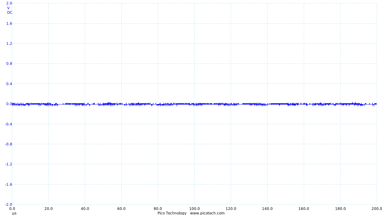
Vin:
Enable:
Feedback:

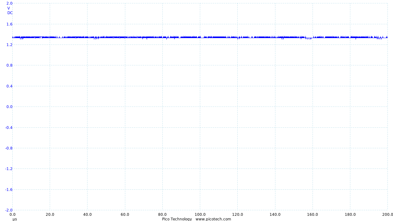
Switch: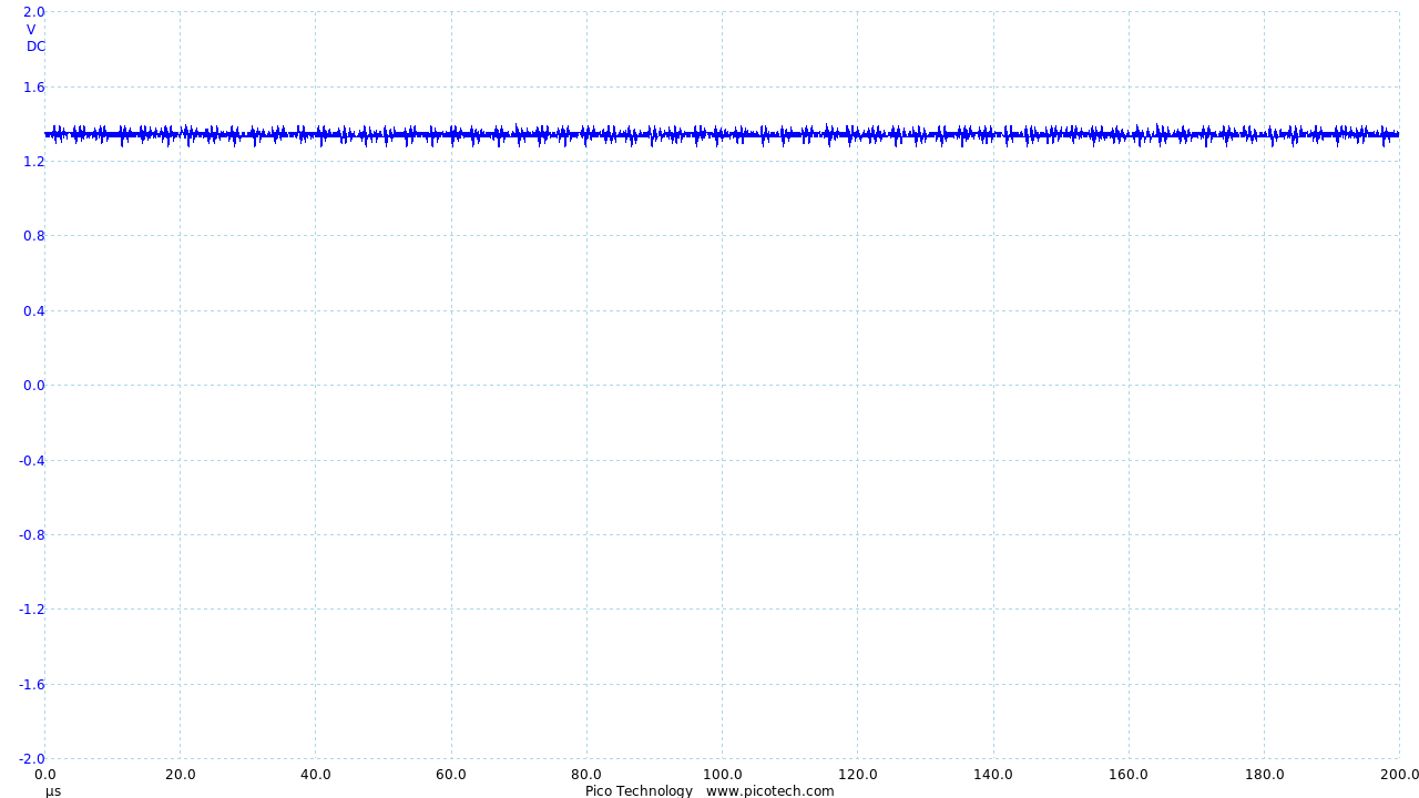
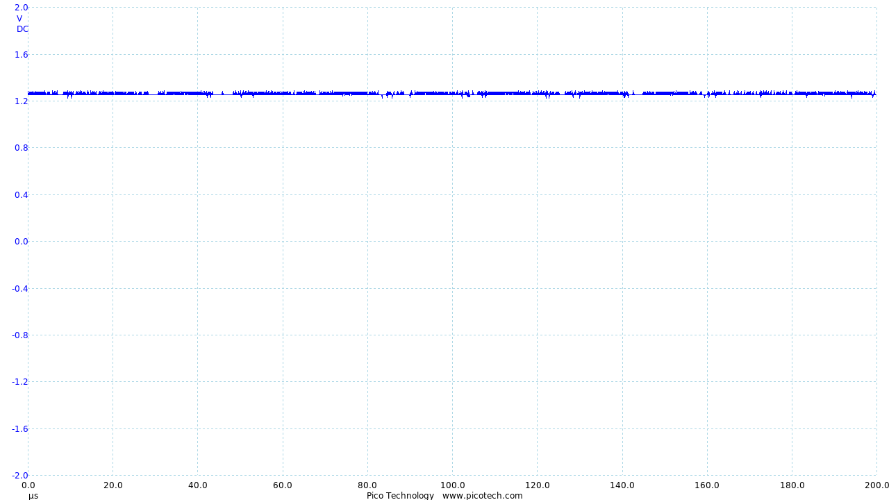
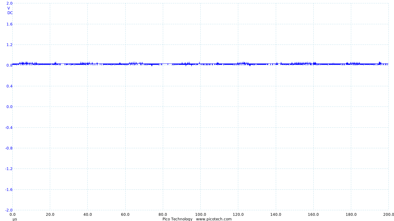
Vout:
Ground:
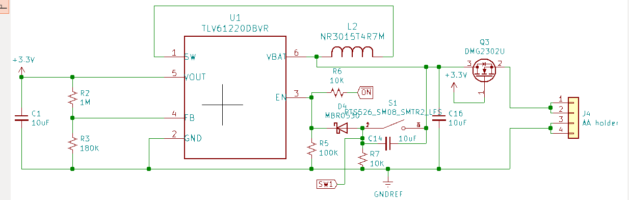
Schematic:
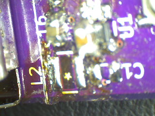
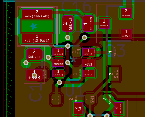
Layout:
I've probably missed something simple, but better to ask for help at this point. Thanks!