This thread has been locked.

If you have a related question, please click the "Ask a related question" button in the top right corner. The newly created question will be automatically linked to this question.

TPS92638-Q1: Iout shuts down at low input PWM duty cycle

Part Number: TPS92638-Q1

Hello TI

I am making this post as I was suggested to do so by TI customer support.

I am using the TPS92638-Q1 in a design, the schematic is identical to the one in Figure 38 in the data sheet, the only differences are TEMP connected directly to GND and each channel connected to a single LED.

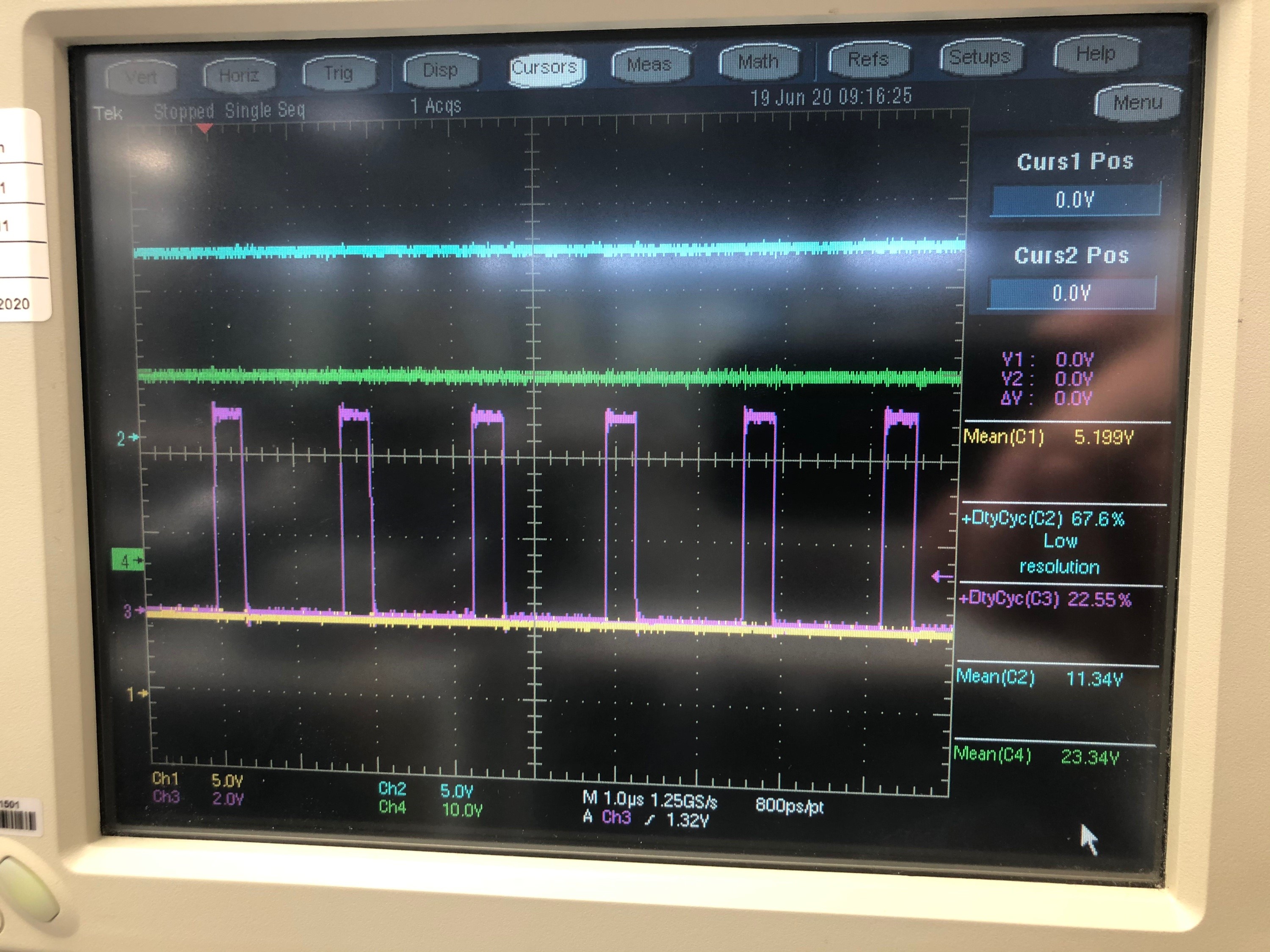
The supply voltage is 24V, the input PWM waveform is a 0 to 5V square wave.

The application requires the LEDs to be dimable from the maximum current, as defined by the resistor at the Ref pin, down to completely off by using an input PWM with 0-100% duty cycle.

However, in the lab, I observe that a decrease in the input duty cycle down to a few percent, shuts off the output and the FAULT pin goes low. A power cycle is required to toogle the FAULT pin and enable the output again. I suspect that the IC interprets the low output as a short due to the low output voltage. Is my understanding correct?

Looking through the data sheet I see, in section 7.5 under “CURRENT REGULATION (IOUTx)” that the minimum current is 2 mA.

In section 9.3.2 of the data sheet, it is stated that grounding the PWM input shuts of the corresponding output channels.

My thought was that an input duty cycle of 0% would be the same as grounding the PWM input (same potential), and hence the outputs should turn off, but this does not seem to be the case?

Please advise.

Lars

  • Hi Lars,

    Do you mind share the waveform of the supply,fault, pwm and output. 

    i want to see the normal and issue condition, that will help me to analysis this case, thx.

  • Hi Frank 

    I took some pictures of the oscilloscope yesterday. They are included in this post.

    Unfortunately, I did not include the supply, but it has most likely not been affected, i.e. 24V.


    Normal condition:


    Fault condition:


    Yesterday afternoon, I changed one of the LEDs at the output and since then I have not been able to dim the LEDs. The output just stays on at the max current of 20 mA (as programmed by the resistor at the REF pin) regardless of the input PWM. Please see attached oscilloscope screenshots with ~80%, ~20% and ~10% input duty cycle. However, I see the same behavior as when I was able to dim the LEDs, at low input duty cycles, the output shuts off and the FAULT pin is pulled low. I checked the equivalent DC voltage at the input with a multimeter and the output shuts down and the FAULT pin is pulled low at 650mV rather precisely.


    ~80% input duty cycle:


    ~20% input duty cycle:


    ~10% input duty cycle:


    Why am I suddenly unable to dim the outputs?

    And is the IC simply not made to support very low duty cycles?

    Does the IC not support dimming to off?


    Regards Lars

  • Hi Frank

    FYI, I’ll try to replace the IC and see if I that helps on the dimming. If you have any idea why the IC would not respond to the PWM, please let me know.

    I am also thinking of a possible workaround wrt. the fault at low input duty cycles. Could I use the enable pin to disable the outputs at low input duty cycles, say less than 10%? Would this cause a fault when enable is low?

    Regards

    Lars

  • Hi Lars

    First, i think it's no meaning to consider duty cycles individually u should consider the PWM frequency at the same time, the out put have a min on and off time if the PWM on time is less than that the out put wouldn't open. 

    i recommend u to reduce the pwm frequency and try again.

    Second,  when the enable is low the device wouldn't detect fault anymore.

  • Ok, do you recommend a specific PWM freqency? In the data sheet, I can see that 1 kHz is used.

    /Lars

  • i want to know your frequency setting first, and the min duty cycle u need.

  • Currently the PWM frequency is set to approx. 2.5kHz, but I can easily reduce it if necessary. The requirement for the application is that the LEDs must be dimmable down to completely off. If this isn’t possible by reducing the PWM duty cycle to 0%, i.e. grounding the inputs, then I have the option of using the enable pin to shut down the chip under a specified Input duty cycle.

  • FYI, my dimming is functioning again. My issue was an open resistor, causing the PWM frequency of the LTC6992-1 to go to 600kHz.

    Replacing this resistor caused the PWM frequency to return to the expected 2.5kHz, which made dimming function again.

  • ok, if you have any other question let me konw