This thread has been locked.

If you have a related question, please click the "Ask a related question" button in the top right corner. The newly created question will be automatically linked to this question.

TPS54320: The way to use TPS54320 RT/CLK pin for external synchronization

Part Number: TPS54320

Hello team,

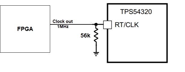
I am considering how to use TPS54320  1MHz external clock to decide switching frequency. I designed below block diagram. 

During power on,  I set IO of FPGA IO as Hi-Z and TPS54320 power on by internal clock set by RT(56k). But the leak current from FPGA is too large during Hi-Z, and the current in RT/CLK pin changed from the desired current value, the switching frequency was increased. So I am considering how I should configure RT/CLK pin.

Would you please advise me to avoid increase switching frequency and  best configuration between RT/CLK pin and FPGA output?

Your support would be so appreciated.

Best Regards,
Akihisa Tamazaki


  • Hello,

    How the Io of the FPGA is driving current when is set to HZ? I would check the setup of the FPGA and make sure it is really HZ. Hz supposed to act as an open circuit between the FPGA and device pin. If the FPGA is set to High Z properly, the TPS will see an open circuit to the GPGA and device works in RT mode and the switching frequency is set by RT resistor. When the FPGA CLK is pulled above the RT/CLK high threshold (2.0 V), the device switches from the RT mode to CLK mode. The device will be then driven with the FPGA. Make sure the square wave clock signal to the RT/CLK pin has a duty cycle between 20% and 80%. The clock signal amplitude must transition lower than 0.8 V and higher than 2V.

    Thanks!

    Tahar

  • Tahar-san,

    Thank you for your comment.

    I will use 3-state buffer to avoid leak current to RT/CLK pin.

    Best Regards,
    Akihisa Tamazaki