This thread has been locked.

If you have a related question, please click the "Ask a related question" button in the top right corner. The newly created question will be automatically linked to this question.

TPS25942A: Difference between Imax and Ilimit

Part Number: TPS25942A
Other Parts Discussed in Thread: TPS25942EVM-635

Hello,

I have downloaded and used the TPS2594x Design Calculation Tool (TPS2594x-Calculation Sheet V1p0.xlsx).
There are Imax and Ilimit columns, but Imax is not mentioned in the data sheet.

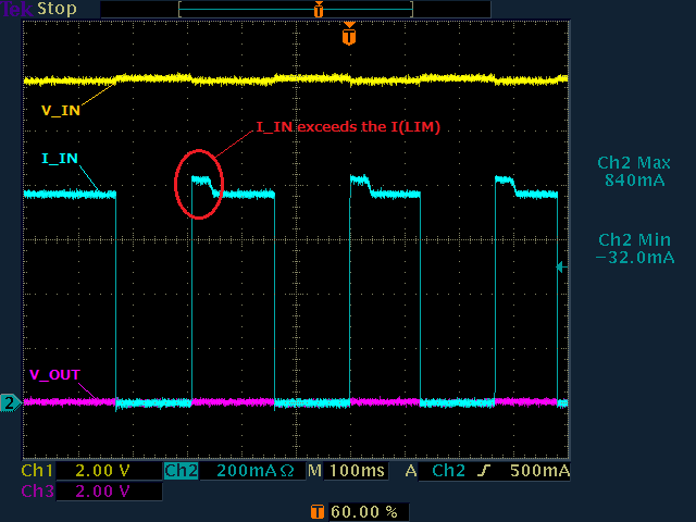
If Ilimit is set to 0.82A, Imax will be displayed as 0.68A.

Is it possible to keep the current exceeding Imax flowing?

For example, set Ilimit to 0.82A and keep 0.8A flowing.

Best Regards.
Yasuhara

  • Hi Yasuhara,

    Imax = The maximum Load current in your system

    Ilimit = The typical current limit setting value

    The current limit accuracy there will be a minimum value of current limit as highlighted below.

    The current limit setting should be selected such that the maximum load current is less than the minimum value of the current limit setting. Else, the load current can be limited by the current limit operation of the eFuse to the load. 

  • Hi Praveen,

    Thank you for the reply.
    Please let me ask you further question.

    The following waveform is the waveform of auto-retry after shorting V_OUT to GND.

    The settings for V_IN, V_OUT, R(LIM) and I(LIM) are as follows.

      V_IN = 12V
      V_OUT_ = GND-short
      R(LIM) = 110Kohm
      I(LIM) = 0.68A(min) ~ 0.81A(max)

    When auto-retry started, I_IN slightly exceeded the MAX value of I(LIM) (0.81A). After about 30ms, it settles down to 0.77A.
    Is this behavior correct?

    Is I(LIM) set to 0.77A?

    Best regards,
    Yasuhara
  • Hi Yasuhara,

    The waveforms you are observing are as expected. This because,

    If during current limit, power dissipation of the internal FET PD = (V(IN) – V(OUT)) × I(OUT)] exceeds 10 W, there is an approximately 0% to 5% thermal fold back in the current limit value so that I(LIM) drops to IOS. Eventually, the device shuts down due to over temperature.

  • Hi Praveen,

    Thank you for the reply.
    Please let me ask you further question.

    【Question 1】
    ・In the auto restart waveform attached to the previous question, I_IN exceeds I(LIM)MAX before thermal fold back works during auto restart. Is this correct?

    /////////////////////////////////

    【Question 2】

    If I_IN is between I(LIM) and I(FASTRIP), how many seconds after I(LIM) is exceeded, the current limit operation will start?
    Is there a formula or table?


    The following figures (Fig.1 and Fig.2) are the peak current waveforms at system startup.


    Fig.1                                       Fig.2

    The settings for V_IN, R(LIM) and I(LIM) are as follows.
    V_IN = 8.1V
    R(LIM) = 110Kohm
    I(LIM) = 0.68A(min) ~ 0.81A(max)

    If the current is limited by the peak current at system startup (Fig. 1, Fig. 2), the system will not start up, so I do not want to perform current limiting operation at the peak current at system startup.
    It exceeds I(LIM), but luckily the current limit is not working in Fig.1 and Fig.2.  I think it's because the time over I(LIM) is short.

    I am concerned that the current limit works under the conditions of Fig.1 and Fig.2 due to the variation of the sensitivity of TPS25942.

    //////////////////////////////////////////////

    Best regards,
    Yasuhara

  • Hi Yasuhara,

    1. Before commenting on your Question 1 , I would like to check your RILM value, Is it 110 kohms.

    • What is the accuracy of the Rilim resistor used ?
    • What is the accuracy of the measurement equipment used  ?   Has been degaussed to remove offset errors ?

    2.The waveforms you shared look like the device output is already up and an over load is applied , correct ?

    • Current limit circuit may take few 100's of us to restrict the over current to current limit value. This response time depends on various factors like % over load, input voltage, output capacitance etc..
    • During initial Vin startup, there can be current flowing into the input capacitors (to charge them to Vin) and this current is not regulated by the efuse. This current can be higher than set current limit.

  • Hi Praveen,

    1.
    -The RILIM  is 110 Kohm. Resistance accuracy is ±1%.
    -The accuracy of the measuring device is about ±20mA. It is degaussed and the offset is adjusted to 0A.

    2.
    -At the time of the shared waveform, it seems that the over load current limit is not applied.
    The waveform where I_IN has risen to 1.04A is the waveform at the timing when 3.3V output in the circuit started.
    The waveform that I_IN has risen to 0.77A is the waveform at the timing when the USB_VBUS output in the circuit starts.
    V_OUT drops by several hundred millivolts when the current fluctuates, but this seems to be a voltage drop due to the internal resistance of the diode or Nois Filter provided between V_IN and V_OUT. ‥
    The actual circuit is as follows.
    (V_IN -> Diode -> e-fuse -> Nois Filter -> V_OUT -> …)

    Best regards,
    Yasuhara
  • Hi Yasuhara,

    Thanks for sharing this information. I will get back to you with my comments by Monday, 29th June. 

  • Hi Yasuhara,

    Can you please remove the noise filter in the path and take the same measurements ? This is to see the affect of noise filter on the circuit parameters measured. 

  • Hi Praveen,

    It is difficult to remove the noise filter. Because there is only one board at hand, it cannot be modified so much.
    Instead, I changed the voltage measurement points to the IN and OUT terminals of the e-fuse and measured the waveform.
    (V_IN -> Diode -> (measurement point V_IN2) -> e-fuse -> (measurement point V_OUT2) -> Nois Filter -> V_OUT -> …)

    Fig3: Auto-retry after shorting V_OUT.        (V_IN = 12V,   R(LIM) = 110Kohm)

    Fig4: 3.3V output start timing.   (V_IN = 8.1V,   R(LIM) = 110Kohm)

    Fig5: USB_VBUS on timing.     (V_IN = 8.1V,   R(LIM) = 110Kohm)

    Best regards,
    Yasuhara

  • Hi Yauhara,

    It is difficult to review the behavior of TPS25942A without the noise filter removed and tested.

    1. Can you try applying short circuit immediately after the efuse (before the noise filter) and check the device behavior ?
    2. Also, where are you measuring the current ? Please make sure that you are measuring the current in a point where there are no parallel paths including device input and output capacitors. It can so happen that you are measuring the current flowing in the device + current flowing into/out of the capacitors.

  • Hi Praveen,


    I applied the short circuit immediately after the e-fuse and checked the device behavior.
    The current is measured between DC Power supply and V_IN2.
    In this measurement (fig7,fig8,fig9), power is directly supplied to V_IN2 immediately before e-fuse.
    In the previous measurement (fig1~fig5), power was supplied from V_IN.

    The input capacitor is less than 0.1uF.

    Fig6: Short circuit measurement

    Fig7: Auto-retry after shorting V_OUT2.        (V_IN2 = 12V,   R(LIM) = 110Kohm)

    Fig8: 3.3V output start timing.   (V_IN2 = 8.1V,   R(LIM) = 110Kohm)

    Fig9: USB_VBUS on timing.     (V_IN2 = 8.1V,   R(LIM) = 110Kohm)


    Best regards,
    Yasuhara

  • Hi Yasuhara,

    Thanks for sharing the waveforms. One thing to keep in mind is that the input current you are measuring is the sum of current flowing into the IC + current flowing into the input capacitors. During steady state the current flowing in and out of capacitors will be zero. But in transient conditions, capacitors do provide/take some current. So, during transient conditions, the input current measured is not equal to the current flowing in the IC. The waveforms we provide in the datasheet are taken in such a way that we only capture the current flowing in the IC. One way to do that is to remove the output capacitors and measure current flowing into the load.

    In case you cannot measure only IC current, you can test it on TI EVM. Do you have TI EVM with you ? 

    • If yes, I would recommend you to test the same configuration on TI EVM with the IC on your board. This will clear out if the problem is with the IC or your circuit. 
    • In NO, I can help you with the measurement for your test conditions on TI EVM. I will require your schematic of TPS25942 for this. Considering the COVID-19 situation, it will take me atleast 3-4 days to test your circuit condition and share results with you.

  • Hi Praveen,

    I have TPS25942EVM-635.
    I removed C2, C3, C4 of TPS25942EVM-635 and set Rlim to 110Kohm and tested.
    The current value measured at Vin1 and the current value measured at Vout1 were almost the same as in Fig. 7.

    I didn't understand the calculation of I(lim) correctly. Are the following recognitions correct?
     TPS2594x-Calculation Sheet V1p0.xlsx Ilimit final (cell B40) Is I(lim)typ instead of I(lim)max.
     When Rlim=110Kohm, will I(lim)min=743mA, I(lim)typ=809mA, I(lim)max=875mA?

    Best regards,
    Yasuhara
  • Hi Yasuhara,

    Yes, you can consider the accuracy to be around 8.5% for current limit setting of Rilm = 110 kohms. Considering the typical current limit value of 810mA, you can calculate the min and max current limits.

    In case you are testing the device with electronic load, Can you please test the device with Resitive load ? Current limiting behavior of the IC is not recommended to be tested with electronic load in CC mode.

    Also, do you have have any current limit set  in your source power supply ? Please increase it to a higher value ,say 2A.