This thread has been locked.

If you have a related question, please click the "Ask a related question" button in the top right corner. The newly created question will be automatically linked to this question.

removing BQ78PL114 EV kit input transistor

Other Parts Discussed in Thread: BQ78PL114

hi everyone

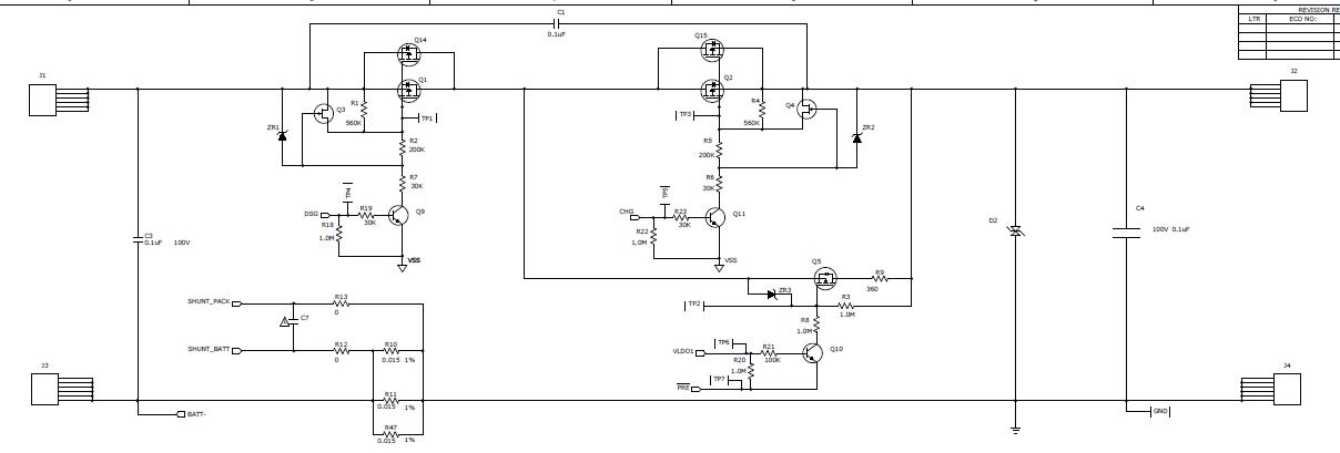
I am working on BQ78PL114 EV kit. This device is amazing, monitors and controls both discharge and charge of battery. But I have a problem. I have a load that needs 110 Amper current and 33.6 Volt. My problem is following: When the load is drawing 110 amper current, Are the input transistors capable of it?       Are the Input transistor  durable to this current level? [ I mean Q2, Q15 ,Q14, Q1 are input transistor ]. In second situation I want to disgard precharge and some charge-discharge controlling units to overcome high current. My second  is, if I dont use CHG , PRE , DSC pins ( I mean when they are not connected in design) and I remove transistors (Q2,Q15,Q15 ,Q1) and put a power line directly to J1, does the device work ? thanks

the picture is taken from http://focus.ti.com/lit/ug/sluu335a/sluu335a.pdf ,  page 40

  • I mean, are  CHG, PRE and DSC pins only for safety operation? Assume that, In a design of BQ78pll114;  CHG, PRE and DSC pins are not connected, and If we use a direct wire instead of using transistor, Will the device work ? thanks

  • Omer,

    This should work but you will need to disable some of the Second-Level Protection features so the '114 doesn't try to turn everything off (like balancing, etc.) and essentially shut down. Check the Technical Reference document for the Charge/Discharge Protection MOSFET Verification features, and any others, that might cause problems if the current is still flowing after the '114 tries to turn it off (by toggling CHG, DSG, or PRE).

    It sounds like you know this but, just in case, you lose all your protection features if you remove the MOSFETs.

  • According to the EVM User's Guide, it's rated for 30A continuous.

    You can increase that by fan-cooling the heat sinks, and/or using more efficient heat sinks, but I don't think you'll get all the way up to 110A. The PCB traces, even with fan-cooling, might not be able to handle 110A either.

    Other options include replacing the MOSFETs, creating your own MOSFET array, or (as you mentioned) just removing the FETs. But you still might be limited to what the circuit board traces can handle. Probably best to just create your own board that can easily handle the 110A load.