This thread has been locked.

If you have a related question, please click the "Ask a related question" button in the top right corner. The newly created question will be automatically linked to this question.

CSD18510Q5B: About the ouput waveform of MOSFET drain

Part Number: CSD18510Q5B
Other Parts Discussed in Thread: CSD17307Q5A, TINA-TI

Hi,

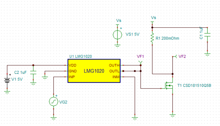
   Pls look at the below schematic of pulse driver,i simulate LD with R1:

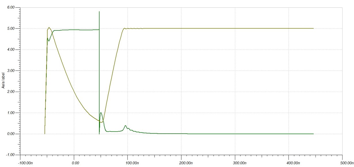
The drain waveform when MOSFET is on:

Than  i changed the R1 into 10mΩ,the waveform is:

Comparing the above two waveform,why the falling edge of sencond is more slow than the first when the drain current is high?

How to improve it when working in high current?

  • Hi Suy,

    Thanks for the inquiry. I will try to run the simulations myself to determine why you're seeing this behavior. I assume this is also related to your other post on the CSD17307Q5A. I will send you a follow up response as soon as I have more information to share with you.

  • Hi Suy,

    I replicated your simulation in TINA-TI and I believe it is correct. However, the simulation is not realistic since you're applying R1 + rds(on) of the FET across the 5V, VS1. With R1 = 200mOhm, the drain current is limited to about 25A (5V/201mOhm) which the FET can support. When you reduce R1 to 10mOhm, the drain current is about 5V/11mOhm = 454A. The simulation allows this but of course the FET and the 5V source cannot practically support this much current. The timing is driven by the rise time of the drain current which takes on the order of 3us for R1 = 10mOhm and on the order of 10ns for R1 = 200mOhm. Based on your earlier post, I believe you're driving a laser diode with this circuit. You will probably want to add the diode to your simulation in order to get more realistic results. Also, keep in mind, the simulation can give you unrealistically high currents based on the value of R1 since the 5V source, VS1 is ideal and not current limited. I'll take a look at your earlier post and run some simulations as well.

  • Hi John,

       Thanks for your suggestion.

       I have tried to use LD to simulating but i have not the a simulation model of LD currently in use,so i had to use R1 simulate LD.

       The LD currently in use impedance is about 10~20mohm and it works in high power mode,the instantaneous current is above 200A.


  • Hi Suy,

    I am going to close out this thread since we are continuing this discussion on regular email.