This thread has been locked.

If you have a related question, please click the "Ask a related question" button in the top right corner. The newly created question will be automatically linked to this question.

LM27313: tft backlight voltage

Part Number: LM27313

Hello forum,

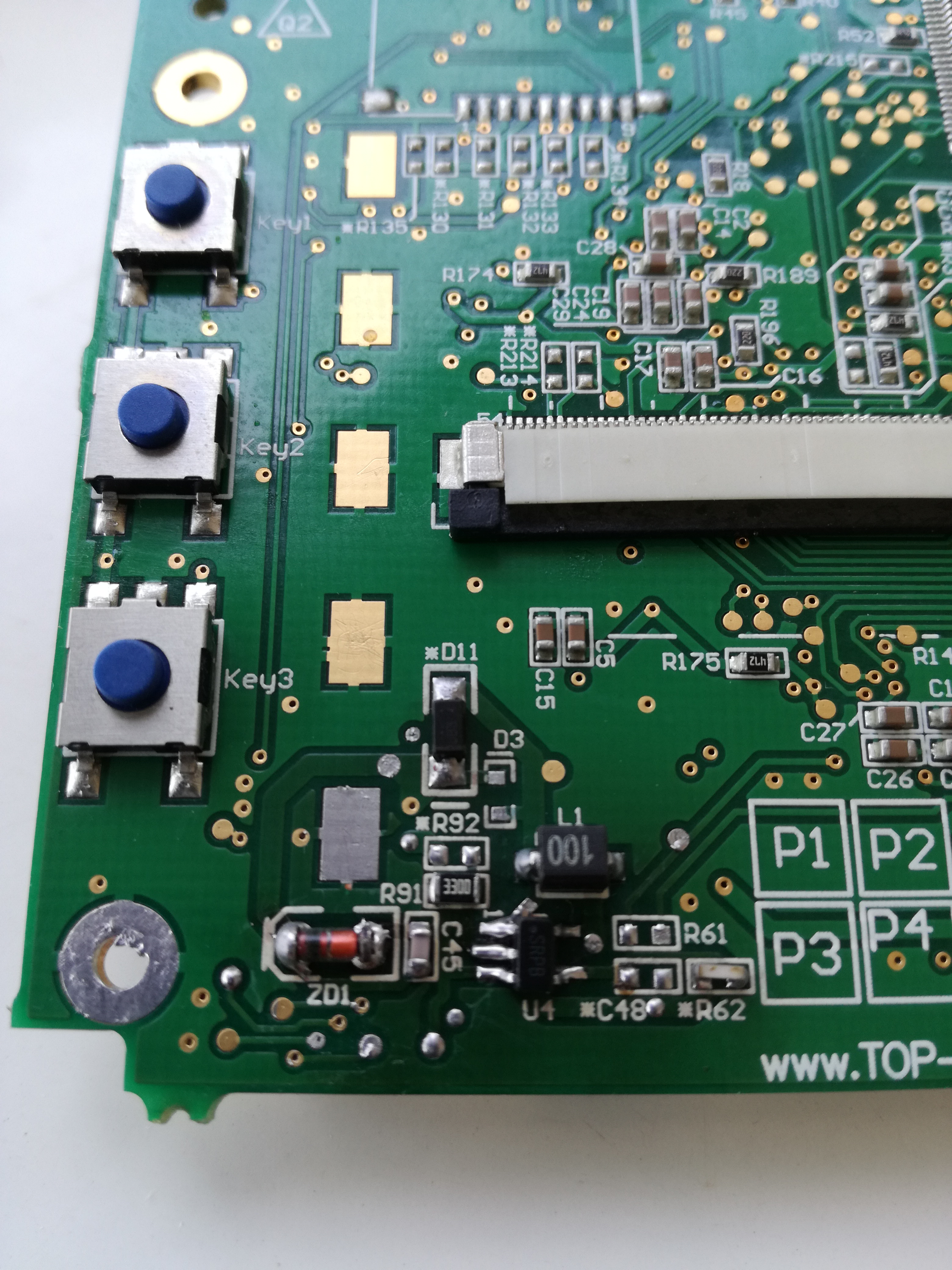
i have a problem with a pcb that drives a tft display on a coffee machine. The LM27313 ic was burnt on pin SW output voltage. So i replaced the ic. There is an input voltage of about 12 volts and the output is the same.

The Display needs a backlight voltage of about 19 volts. So it doesn't lights. The backlight is ok i tested with external voltage.

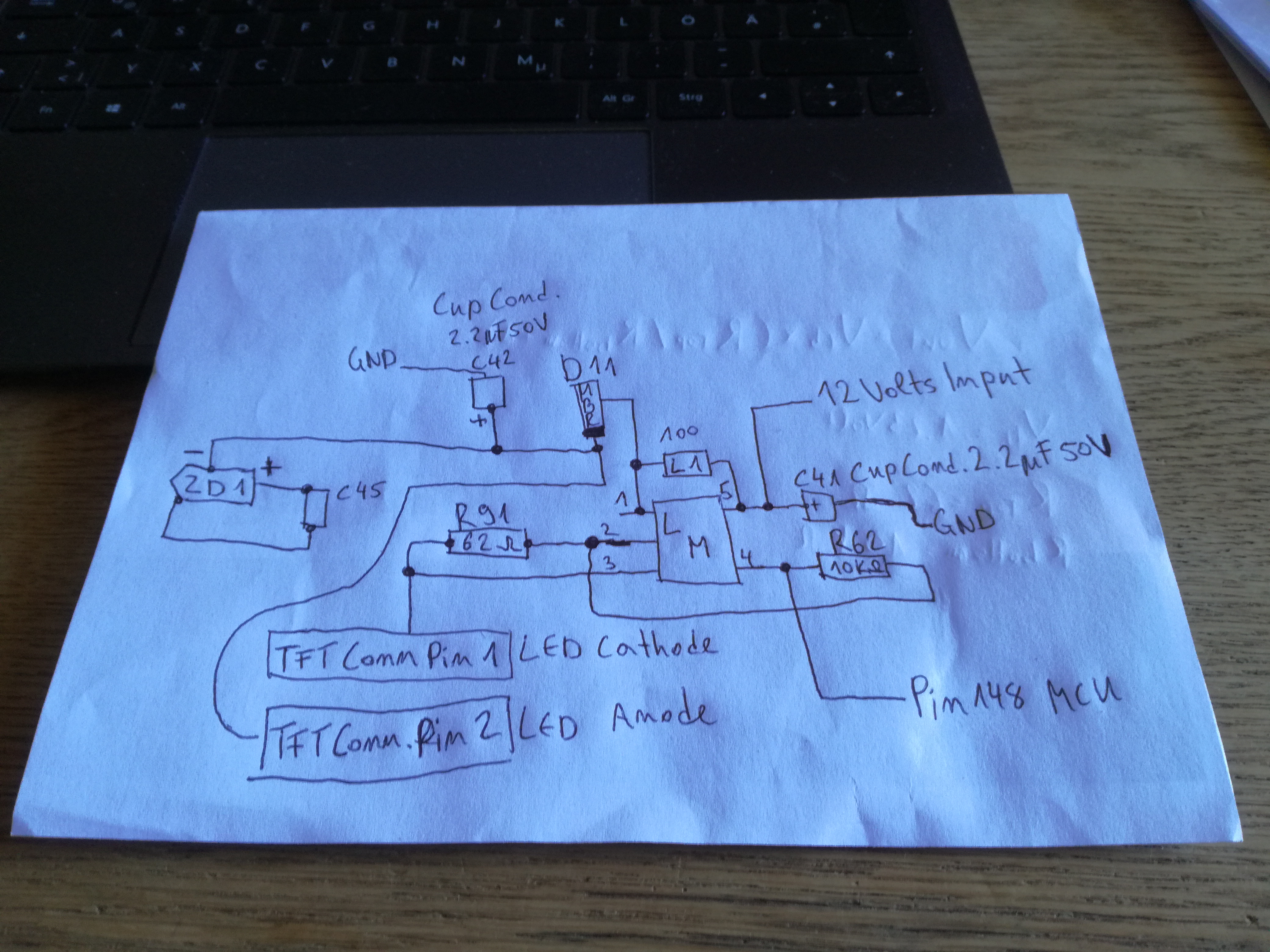
There is a 10 kohm between SHDN pin and GND and a 62 ohms resistor between the GND and FB pin. There is a coil between Vin and SW and further a shottky diode.

In my understanding the LM27313 is a stand alone ic which isn't driven by an cpu or others pieces.

In the datasheet there are some example circuits with 5 volts input. Is the calculation for output the same as for 12 volts input ?

Hope you can help me. If you need more details please write. Thanks.

Paul

  • Hi Paul,

    Can you share the full schematic and layout please? 

  • Hello Zack,

    thanks for your reply.

    The pcb is quite complex so i cannot give a layout or circuit diagrams. I can try to post a picture of the board.

    The info i found from jura company who produces the machine is as follows...

    4-layer pcb

    Renesas mcu SH7264

    54 pin fpc connector to tft

    core supply of 1.2 volt DC

    Flash 32 mb

    1 serial communication channel to rotary pcb uart 3.3 volt (the rotary board has the power on button and some other buttons and the rotary switch)

    1 serial communication channel to main pcb uart 5 volt

    3.3 volt from rotary pcb

    VDD power supply from rotary pcb for tft backlight

    STEP-UP Converter for tft backlight in CONSTANT CURRENT operation

    uart driver 5 volt levels for serial communication between tft-pcb and main pcb

    Backlight dimming

    SPI Interface between TFT element and MCU

    The tft is a TM035kdh03

    I dont't understand how the backlight dimming could be made.

    All the voltages 3.3 and 5 and 12 are present. The 1.2 volt is made by a LD1117A.

    The Step-UP i think isnt made.

    Regards, Paul

  • Hi Paul,

    Thanks for these information.

    You could only share the LM27313 part schematic and layout, not the whole system.

    The issue is only related to the step-up converter. From your early description, the SHDN pin is connected to GND pin with a 10kohm resistor. You have to set SHDN pin to logic high to enable the regulation, so you can use a DMM or oscilloscope to probe the SHDN pin voltage first.

  • Hello Zack,

    as you mean, the shdn pin is low and therefore the booster is not working. Ok, should i then connect the Vin pin to shdn pin directly or via a resistor ? On the board there seems no such resistor to be.

    i don't know "logic high".

    I upload a picture. The R91 is originally a 62 ohm resistor. I replaced with 330 ohms to see what would happen, well, there happened nothing.

    The R62 is the 10 kohms. D11 is the shottky MBR0530.

    On the other side of the pcb there are some cup capacitors i think for stabilization.

    Regards,

    Paul

  • Hi Paul,

    The layout is not good. Normally the switch loop should be as small as possible, but as you see, the switch loop composed of IC, schottky diode D11, output capacitor is really long. And what's the reason of putting the component ZD1? Can you share the schematic?

    Below is an example of recommended layout.

    I mean can't you check how the SHDN pin is connected by looking at the schematic? I guess the SHDN is controlled by the MCU. 

  • Hello Zack,

    you are right, there is one connection from shdn pin to the mcu, the eye just below the marking C27 goes to Pin 148 to it. The mcu has 208 pins. I don't have the datasheet for the mcu so i don't know what it does. Perhaps for dimming or stand by ?

    The ZD1 and C45 are loop closed. From kathode of the shottky to kathode ZD1 to C45 to Anode of ZD1.

    Originally the shottky was on field D3.

    I could desolder all the parts involved within the LM27313 and make a hand drawing of the layout if that would help.

    Regards, Paul

  • Hi Paul,

    1. Can you draw a schematic of how ZD1, C45, D11 are connected?

    2. If the MCU doesn't pull the SHDN pin to logic high, then LM27313 circuit could never be enabled and output the correct voltage. To debug the LM27313 circuit, you can solder a wire at SHDN pin to pull this pin logic high with external power supply. But to understand why the MCU doesn't set SHDN pin to high, you may need to contact the original PCB manufacturer and read the code.

  • Hello Zack,

    i can make the schematic tommorrow when i am in my laboratory.

    As i wrote earlier, the LM27313 was slightly burnt on pin SW perhpas through water or vapor in the machine. Could this be misfunction pin shdn and the mcu.

    As in the datasheet described i could make connection Vin to shdn, so shutdown will be deactivated. But then, do i have to cut the path to the mcu because of the high voltage ?

    And still i have the question about calculation of output voltage for 12 volts input and the two resistors 62 ohm and the 10 kohms.

    Thanks so much for your help.

    Regards, Paul.

  • Hi Paul,

    My meaning is the mcu should set SHDN pin to high to enable LM27313. For debug purpose, you can connect SHDN pin to VIN. 

    The calculation of output capacitor: Vout= Vfb*(Rtop/Rbottom+1), where Vfb is 1.23V, Rtop is the top resistor of the feedback path, Rbottom is the bottom resistor of the feedback path.

  • Hello Zack,

    i resoldered original resistors 62 ohm and 10 kohms and tied Vin to shdn pin and cut the path to mcu. The output voltage was varying between about 17 to 24 volts in a regular form. I have DMM only to measure.

    The Lm27313 was getting very hot and possibly died by this action.

    Regards, Paul

  • Hi Paul,

    Have you drawn the schematic and could you show me the 62ohm, 10kohm, ZD1 place in this circuit? So that I can help analyze. 

  • Hello Zack,

    here is the drawn schematic...

    Regards, Paul

  • Hi Paul,

    It really helps me to understand your circuit.

    LM27313 is configured working at constant current mode by connecting a 62ohm resistor from FB pin to GND. As the converter is always regulating the FB pin to 1.230V, the TFT and R91 path will flow a 1.230 V / 62 ohm = 19.8 mA current. You must connect the TFT, otherwise the converter output voltage will be very high and burn the low-side FET. Did you connect the TFT display when you test the board last time?

    Secondly, the output capacitor C42 placement didn't follow our datasheet recommended layout. It will cause high PCB parasitic inductance and SW pin switching spike increases. This is a possible failure reason.

    Third, could you capture some waveforms, such as VIn, SW, Vout, FB? 

  • Hello Zack,

    in the test i didn't connect the tft screen. I will solder a chain of 6 or 8 LED's together and link to the connector to see what will happen. I still have on LM27313 that is new.

    I only have a simple DMM so i cannot see waveforms.

    For C42 i cannot do much i think.

    Will make the test today...

    Regards, Paul

  • Hello Zack,

    i made the test with 9 common green LED's linked together. By power on the LED's start flickering with a voltage varying from about 14 to 18 volts. Each test was about 30 seconds. The LM27313 was getting hand warm.

    After replacing two cup conds on the other side of the pcb, by power on there was a short flash and since then the LED's are not flickering any more. They keep dark. LED's are ok.

    What i also found is: the input voltage from the rotary board is also slightly varying from about 11.5 to 12.5 volts. How is the LM27313 handle this ?

    Regards, Paul

  • Hi Paul,

    It's not easy to debug the circuit without a digital oscilloscope. We need the waveform to check the key net waveform so that we know what's happening.

    The 11.5 to 12.5V input voltage should be ok for LM27313 because the converter will change the low-side switch duty cycle dynamically to generate a wanted output voltage.

    It's better to generate a new version layout and follow the recommendations. 

  • Hello Zack,

    sorry for delay. And thanks so much again for your help and patience with me as really not being an expert.

    I will close this project as most probably the pcb isn't repairable.

    Regards, Paul