This thread has been locked.

If you have a related question, please click the "Ask a related question" button in the top right corner. The newly created question will be automatically linked to this question.

TPS549B22: How to set defaut Vout?

Part Number: TPS549B22

Dear TI supporter

I have some question when using TPS549B22.

1、At Page7 of TPS549B22 datasheet,it shaws that the test condition Vbp=2.93V,and is conflict with Page9 Vbp=5.07V typically.And meanwhile,I measured 5v on my DVT,Also Page7 of TPS549B22 datasheet,I set Rlow=75K and Rup=100K and wish can get Vout=1.2557V but I get Vout=1.024V without andy Loading.I want to know how to set the Vout by resistance?

2、If we use MCU to init this Power IC,is there any reference configuration file Ti can support?

3、If we can get Vout=0.95V By HW,what is the difference between HW and SW to config this DCDC

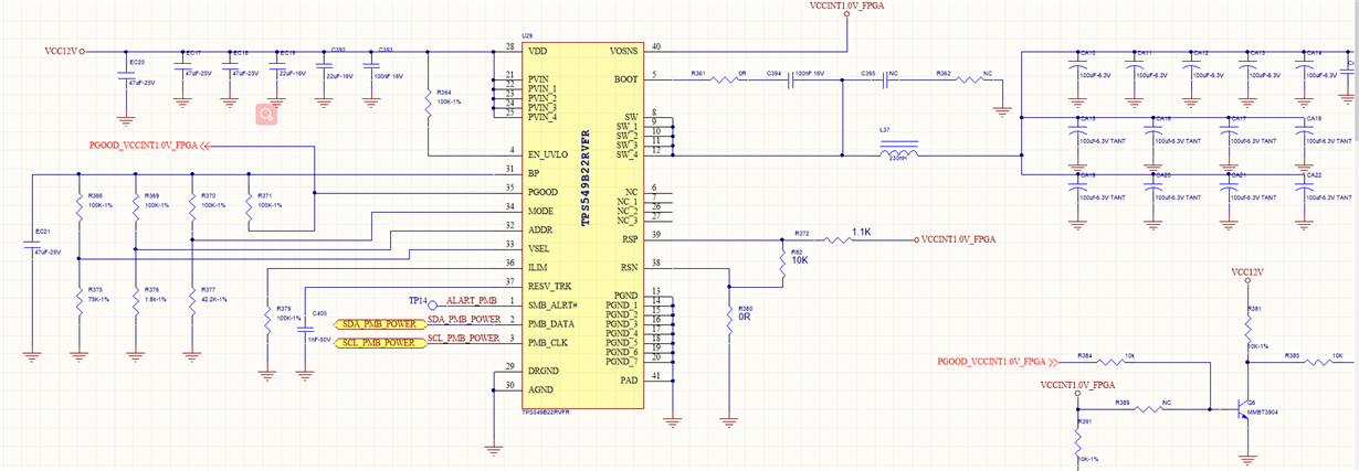
Attached our  SCH

  • add some info:

    when I set Rlow=75K and get Vout=1.048V (NOT 1.024V)without any loading

    but when I add about 250mA loading, Vout will drop obviously(from 1.048 to 1.037V).the actual laoding is Xilinx‘s UltraScale FPGA and maybe need above 10A loading.I am afrain there must be some question in the schemtic

  • Hi

    The TPS549B22 always boots to the voltage defined by the VSEL pin.  So RVSET defines what the BOOT voltage is. The voltages values listed in Table 3 on page 18 of the data sheet http://www.ti.com/lit/ds/symlink/tps548b22.pdf#page=18 for codes 0001 - 1110 are hard-coded voltages.  Codes 0000 (Short to AGND or 1.78k-Ohms) and 1111 (187k or Pull-up to BP) select voltage stored in NVM, which ships from the factory programmed to 0.975V as the default EEPROM value.

    AFter it boots, you can always change the voltage by reprogramming it.


    If the user selects one of the 4 VSEL options that select a reference voltage of 0.975V (Open, Short, 187k or 1.78k) the USER can change the VBOOT voltage by setting VOUT_COMMAND and storing that value to NVM using STORE_DEFAULT_ALL.

    Regards,

    Gerold

  • Dear Gerold:

    Thanks for your reply!

    I am sorry I also cannot get the point.

    1、On page 18 of the datasheet,how can I config VSEL[0-4]?By changing different RVSEL or Programing this DCDC chip?And which resistance is Rvsel?

    2、If I want to fix the Vout=0.95V quickly by using resistance  when bring up the DUT .can you share the solution?And as a good power suply for xilinx,what is the best solution you recommended?

    Thanks!

  •  

    To your first message:

    1) The TPS549B22 device's pin strapping uses a resistor divider between BP and AGND to set the pin-strapped values.  The external voltage on the pin will be compared to an internal resistor divider between BP and AGND.  During power-on, the BP voltage will rise to approximately. 3V, which is sufficiently below the VDD UVLO voltage to ensure that the LDO voltage is always in regulation and that the pin-detection is not adversely affected by VDD or BP voltages.  That it why you see two different BP voltages in the datasheet.

    2) You can down-load TI's FUSION Digital Power Designer - https://www.ti.com/tool/FUSION_DIGITAL_POWER_DESIGNER and access the TPS549B22 in off-line mode, configure the part as desired, then export a project file or programmer script to provide a baseline configuration.

    3) Table 2 on page 20 of the datasheet shows the available reference voltages.  code b'1001 is 0.9492V and is selected using a 100kOhm resistor from VSEL to BP and a 53.6k resistor from VSEL to AGND (with a hiccup fault response) or 60.4k with a latch off fault response.  To get an output voltage of 0.9492V, you will need to remove R82 (10k from RSP to RSN) and you should reduce R372 from 1.1kOhm to 100-ohms.  With this divider in place, the output voltage will be above the programmed reference by the voltage drop across the 1.1kOhm resistor.

    If you select 0.9492V reference voltage via pin strapping, the part will always reboot to 0.9492V during power on reset, regardless of the last value stored to NVM.  If you select a Floating (no resistor to AGND) or Shorted to ground (0-ohm resistor to AGND and no resistor to BP) the TPS549B22 will always boot to the last VOUT_COMMAND value stored in NVM by the STORE_DEFAULT_ALL PMBus command, other than their response on a reboot after VOUT_COMMAND has been stored to NVM, they are functionally equivalent.

    Regarding your second message:

    1) Table 2 on page 20 shows the binary code and analog voltages programmed into error amplifier reference.  Rvsel is the resistor from the VSEL pin to AGND when a 100kOhm resistor is connected from VSEL to BP.

    2) To configure the output voltage to 0.95V with R82 = Open and R372 = 100 ohms

        Leave R368 = 100k

        Change R375 to 60.4k (retains the latch-off fault response of the 75k-Ohms)

    If the Xilinx processor needs R372 = 1.1kOhm to do analog adjusting of the output voltage, you will want to set the reference voltage to 0.8496V, so the output voltage will be 0.95V after the RSP to RSN divider.  You would do that by

        Leave R368 = 100k

        Change R375 to 29.4k (again, retaining the Latch Off fault response)