This thread has been locked.

If you have a related question, please click the "Ask a related question" button in the top right corner. The newly created question will be automatically linked to this question.

TPS23756: Reduce Output Ripple / Bode Question

Part Number: TPS23756
Other Parts Discussed in Thread: PMP40514, TLV431, , TPS23758

Thanks to all your advice, my POE adapter is starting to work nicely.

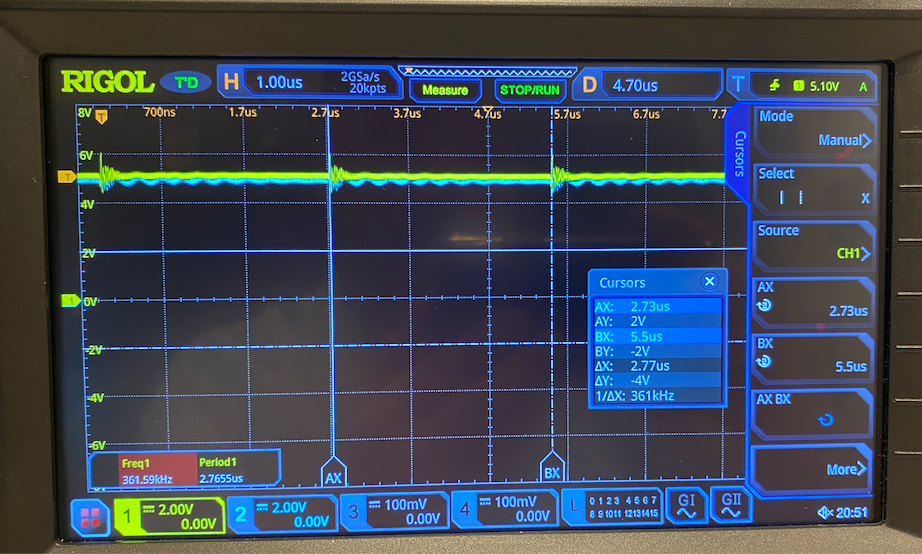
My biggest issue is a 900mv peak-to-peak ripple on the output.  I was wondering if anyone could offer a few things to look at, for example A) Your type-2 compensator is not tuned correctly, or B) something else?

After putting the original specified opto with 80-160% gain and the right 330nH inductor, things are looks great!

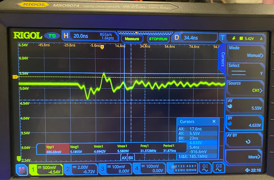
I've tuned the original oscillation by snubbing the output diode (10 Ohm+1nF and/or 10nF) and that really helped.... I think....

At steady state current draw/fairly heavy load 10W+, output is rock solid for 80% of the time other than the switching ripple . (not sure about the instant response over/undershoot, but nothing I can see right now)

Again like before I'm basing my design on the PMP40514 with a different transformer for 5v output (POE13-50).

I started with all values as designated in the original schematic, but admit I've messed around with it a bit to get this far so... who knows.

No matter the current draw, my output voltage is roughly like this (higher draw means more ripple):

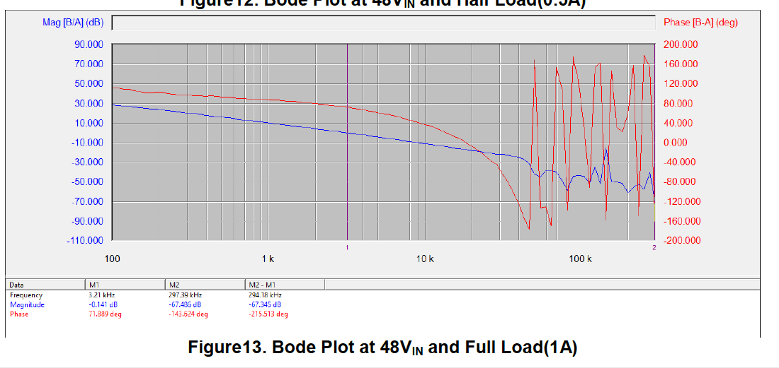
Also at the advice of your team I've got the bode plot at 10W draw (approx)!  Yay!

Clearly this Rigol has a strange scale bug (green vertical doesn't match "real phase") .  But anyways, Gain Margin 20db, Phase Margin 67.91deg.  Does it look sane? Looks sane to me.

Reference from the test report tidt074.pdf

I have a handwound 1:1 transformer (on a budget where possible) for the ripple injection, so maybe it's not perfect.  Not sure how to tell how good my transformer response is.

I noticed that in my bode plot and the PMP40514 Test Report that below 100Hz and above 100kHz that phase and gain start to go a bit all over the place.  In general, is there a frequency range outside which "I don't have to care too much"?.... 

Thankfully as far as I can tell, even with changing loads from 5-10W I can't see anything strange so I assume the magic is working.

Thanks so much for the advice!

Jeff

  • Example output from a different tuning that shows that in general ripple is only at the beginning of the switching cycle. (Yellow line)

    Blue line is the "other side" of the bode injection whachamacallit resistor.

    Just want to show things are mostly fine.

  • Example output from a different tuning that shows that in general ripple is only at the beginning of the switching cycle. (Yellow line)

    Blue line is the "other side" of the bode injection whachamacallit resistor.

    Just want to show things are mostly fine.

  • Hello,

    There two main questions I see here: 

    1. Output ripple is high, what to do about it?

    2. Is my bode plot okay?

    1. To accurately measure output ripple, it must be measured with a tight loop across a ceramic capacitor (if possible). Typically a "tip and barrel" measurement is used. Otherwise the noise from the measurement alone can be contributing to the large noise. Otherwise another way is to filter it out with larger caps. 

    2. The bode looks okay. Outside of 100Hz-100kHz (for most of our reference designs switching at 250kHz) we do not care about the bode plot. Above 100kHz, noise from the length of the cables, the bode machine and other small signals become apparent. That is why the graph will go "crazy." The ultimate goal of the bode plot is to show the system is stable, and can handle load transients. To know if it is "good enough" is to check the load with an electronic load that is switching and see if it meets your project specs. 

    If this post answers your question, please indicate so by marking this thread as resolved. Thank you.


    Regards, 


    Michael P.

    Applications Engineer

    Texas Instruments 

  • 1. Thanks for the tip on the tip & barrel measurement.  I'll do that.

    2. Thanks for the look at the bode plot. Electronic load is coming soon, so transient load verification for our application can be done later.  So far so good.

    Thanks again Michael!

  • oh you'll laugh... 

    so I disconnected the 1:1 transformer

    and... used tip and barrel measurement... 

    and...I get rapid rises to the 5v target, then slope down from there...

    Entertainingly enough... hooking up the 1:1 transfomer... then running the bode plot... fixes the situation (until the next power on).

    Does it sound like anything familiar?  If not, no worries.. I'll keep tinkering.

  • Hello,

    Did you try the measurement at full and no load? 

    This looks like it is in DCM. 

    I am also not sure what you mean by the 1:1 transformer and how you disconnected it? There are two transformers in the design, the input data/power transformer and then the DC-DC transformer. What part are you talking about?

    If this post answers your question, please indicate so by marking this thread as resolved. Thank you.


    Regards, 


    Michael P.

    Applications Engineer

    Texas Instruments 

  • Yeah the waveform looks about the same in both the no load, partial load (3-5w) and "fuller" load (10w).  Just about 50mv difference in Vpeak-to-peak.

    Oh the 1:1 transformer is what I use to inject the AC signal for the bode plot (not part of the official circuit)

    This looks like it is in DCM.  <- Discontinuous current mode?  Do you think drawing more current will kick the circuit into CCM and make beautiful waveforms?

  • (BTW at "maybe DCM" it looks like the waveform on the secondary side is about 65hz?  but if you look at the primary side, you can see the gate drive of Q2 clearly going at the 367khz or whatever the FRS is set to).

  • Hello,

    Thank you for the information. I have not seen the situation where adding the bode measurement equipment fixes the output waveform.

    One thing I would note is to help with output ripple is to increase the output capacitance. Typically 5V designs would have higher output capacitance since they are sourcing more current for the same power level. 

    If this post answers your question, please indicate so by marking this thread as resolved. Thank you.


    Regards, 


    Michael P.

    Applications Engineer

    Texas Instruments 

  • I'll try adding some capacitance and see if it helps.  Thanks for the suggestion!

  • Michael, 

    Good news.  I was able to reduce my output ripple to 400mv Vpp.  I'll try to see if a snubber on the diode helps tomorrow.

    I had the wrong pinout for the voltage shunt so... you can imagine it really doesn't work right. :)

    Thanks a bunch!  Will let you know if I solve the ringing/ripple. :)

    Jeff

  • Jeff,

    Thanks for the update. Glad you were able to get the ripple down. Let us know how it goes!

    If this post answers your question, please indicate so by marking this thread as resolved. Thank you.


    Regards, 


    Michael P.

    Applications Engineer

    Texas Instruments 

  • hahaha would you believe? I was wrong about being wrong about the TLV431... 

    I'm going to table this for a moment because I have some success with the TPS23758 (thanks to your suggestion)... I'll post my question in a different thread.  If that works out, then this TPS23756 can go into my "slow learning bucket"

    Thanks so far!