This thread has been locked.

If you have a related question, please click the "Ask a related question" button in the top right corner. The newly created question will be automatically linked to this question.

BQ25505: Type selection: Output voltage programmable control power supply chip, used to adjust the output voltage of power management chip, for recommendation

Part Number: BQ25505
Other Parts Discussed in Thread: DAC53608

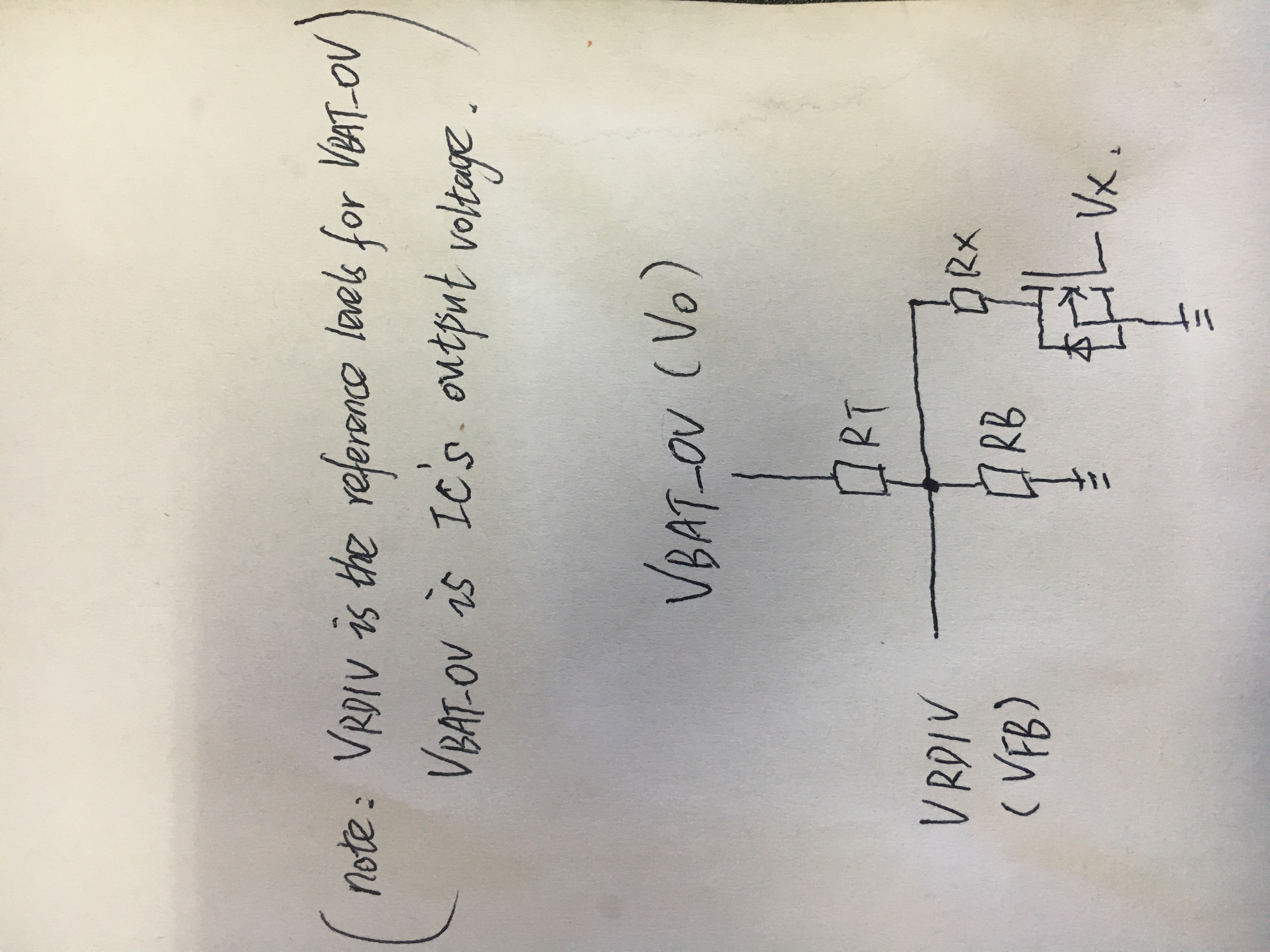
The output range of the front-stage power management chip is 2.2-5.5V, and the adjustable range is around 1V. How to make the output voltage dynamically adjust? With analog power chips? How do You choose an architecture? Please recommend

  • Hi,

    I am not aware of any customer who has made the output dynamically adjustable and we have not tested such functionality.  As shown in d/s figure 32, the output resistors are only sampled every 64ms and compared to the internal reference.  I do not recommend tying a DAC directly to the VBAT_OV pin.  Instead, I recommend using the feedback resistors as shown and add a 3rd resistor from the DAC output to the feedback resistor midpoint.  The appnote at the link below explains how to size those resistors:

    https://www.ti.com/lit/an/slyt106/slyt106.pdf

    Keep in mind the 3rd resistor and bottom VBAT_OV will sink current all the time.

    Regards,

    Jeff 

  • Hi,

    Jeff

    I am very happy to receive your reply,A portion of this feature can be observed in Figure 20 where the VRDIV node is monitored. Here the VRDIV node provides a connection to the VSTOR voltage (first pulse) and then generates the reference levels for the VBAT_OV and VBAT_OK resistor dividers for a short period of time.This means that VRDIV=VFB (dynamic output circuit in the above file), through simulation analysis, VBAT_OV= output voltage of IC, and VBAT_OV=Vo, then my following circuit diagram is correct?Or VFB=VBIAS=1.21V (in bQ25505's data manual, VBIAS= 1.21v)?If so, which DAC should be chosen Regards,
  • Hi,

    Your analysis and drawing is correct.  Alternatively, if your DAC is high accuracy, you could inject the DAC's dc voltage directly through Rx instead of using a FET to switch in the resistor.

    Regards,

    Jeff

  • Hi,

    Jeff

    Thank you for your always support, if the circuit diagram above I understand correctly,  stated on BQ25505 datasheet ROV1 + ROV2 = 13 M Ω, used to set the over voltage threshold, then based on the information you gave me, there are a series of resistance calculation, whether I should keep the original resistance value of the constant , the adjustable voltage circuit resistance is also follow the RB = RT + 13 M Ω, or reset, whether MΩ level of resistance to meet the requirements of the DAC circuit.thanks

    Regards,

  • Hi,

    The resistor values can be smaller than recommended, down to 100kohm total or so.  The high value is improve charge efficiency.

    Regards,

    Jeff

  • Jeff

    Im Sorry for bothering you every time. Thank you again.I have two questions.

    1 look at the data shown in the examples of dynamic adjustment circuit, DCDC has a VFB is a fixed value, such as 1.25 V, in different way, I'm going to the middle point of the connection of resistance points resistance is VRDIV pin, VRDIV once every 64 ms sampling VSTOR  node, and then provide a reference for undervoltage threshold, when seen from the simulation figure sampling (high) time is about 4 V, not sampling (low) is 0 V, as shown in the figure below, FB in DCDC is fixed voltage, which is the internal reference voltage,Can the periodically changing VSTOR be used as a reference for dynamically adjusting circuits?

    2.I have learned that DAC is divided into programmable and non-programmable. Programmable DAC(such as DAC53608) connects to SCM through serial interface (SCL, SDA.i2C), so the power consumption of the system will be high.Is there any non-programmable DAC suitable for my circuit diagram? Could you recommend it for me?I would be most grateful.

    Regards,

    Feng

  • Hi Feng,

    The first pulse reads the current VSTOR.  The second pulse computes 2/3 of desired VBAT_OV value.  Then, internally, the part decides if it needs to continue switching or stop switching, if VSTOR> or < VBAT_OK or if VSTOR < VBAT_UV (fixed internally).   As long as you have adjusted the VBAT_OV resistor divider with your injected voltage, the second pulse should change to be 2/3 of your desired VBAT_OV.

    I am not aware of a non-I2C DAC.  Therefore, you might need to change back to the resistor in series with FET and hi/lo FET gate drive to dynamically adjust the voltage.

    Regards,

    Jeff

  • Hi,

    Jeff

    FB in DCDC is the internal reference source and a fixed voltage, which can be used to calculate the formula in the DAC dynamic regulation circuit. However, VRDIV is a changing voltage (sometimes 2/3 of VSTOR, sometimes 0V) and the sampling changes every 64ms, which cannot be substituted into the formula calculation in the file you sent to me.It's not going to be a benchmark, right?

    So which pin of the BQ25505 chip can I use as the reference voltage of the chip?

    Regards,

    Feng

  • Feng,

    The internal reference is the 1.2XV per the spec table.  VRDIV does not show the reference.  If you change the feedback divider with your injected signal or FET+resistor, the 2/3*VBAT_OV should change to your new value.

    Regards,

    Jeff