This thread has been locked.

If you have a related question, please click the "Ask a related question" button in the top right corner. The newly created question will be automatically linked to this question.

UCC27210: Output gate protection

Part Number: UCC27210

Hi there,

I would like to find out more about protecting the gates on this device from transients and came up on the below post:

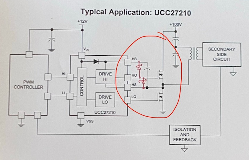
As we are driving the gates from 0-12V I am not sure how the below protection can function using schottky diodes since they pull the voltage down to 0.5V? Would this not interfere with reaching 12V? Please could you help with explaining this which was mentioned by  in the post. I would think that zener diodes would be more appropriate and I was looking into placing SMBJ11A littelfuse diodes with a Vclamp of 18.2 volts between HO and HS of the chip. Would this provide adequate protection from voltage transients and is the Vclamp low enough? Many thanks in advance!

https://e2e.ti.com/support/power-management/f/196/t/880048?tisearch=e2e-sitesearch&keymatch=UCC27211

Steven

  • Steven,

    Thanks for your interest in our driver.

    External Zener clamp diodes from gate to source terminals of the FET is an effective option for protection against electrostatic discharge and transients surges at the gate but the capacitance of the Zener diode might have a slight adverse effect.

    Schottky diodes are generally good for our drivers due to the high frequency switching nature of the applications so long as they're placed as close as possible to the driver IC's HO and HS pins.

    In terms of diodes ratings, you certainly want the diodes Vclamp to be within driver's pins specification. For your case, 18V Vclamp seems reasonable. 

    Regards,

    -Mamadou

  • Hi Mamadou. Many thanks for your reply. Could you explain how the Schottky works as I am not sure how it is compatible with a 12V gate drive? Would it not pull the voltage down to its schottky voltage of e.g 0.5V during normal operation? Meaning instead of the gate voltage changing from 0 to 12V gate voltage amplitude, it would then become 0 to 0.5V gate voltage amplitude?

  • Hi, Steven,

    Maybe this diagram will help. Generally, these are not needed, but in some cases, they can help prevent voltage excursions from damaging the output driver. The schottky diodes help your circuit maintain within the Absolute Maximum Ratings of the driver which is +/-0.3V of the supplies. So, if HO tries to go about HB (the supply for the gate driver output stage on the high-side), it will clamp it to HB+0.3V, where 0.3V is the typical forward voltage of a schottky diode.

    Similarily, these can be applied to the LO output as well. In that case, you would connect them LO to VDD and LO to VSS. I didn't draw them for clarity.

    Let us know if you have further questions.

  • Hi Don,

    Many thanks! This clears it up for me.