This thread has been locked.

If you have a related question, please click the "Ask a related question" button in the top right corner. The newly created question will be automatically linked to this question.

LMR23615: Conception of power supply cluster

Part Number: LMR23615
Other Parts Discussed in Thread: TLV62568, TPS22954, LM76005, LMR33620, TLV62568A, PMP15039, TPS22953, LM76003, LM61440

Hello TI team,

for an embedded project I am looking for a suitable concept for the power supply and a suitable switching regulator selection.

The system basically comprises a 32 bit microcontroller with external flash (QSPI), two RS485 interfaces and a CAN interface. Microcontroller, flash and the two RS485 drivers run on 3.3V. The currently planned CAN transceiver runs on 5V (VCC = 5V, VIO = 3.3V). The current consumption on the 3.3V is below 500mA (worst case scenario). At the 5V, only the CAN transceiver is supplied on board.

Our project also works with an extender board. The power supply for the extender board is provided by our board. The current consumption of the extender board is temporarily 5V / 3A - typical current consumption is around 5V / 1A. The power supply to the extender board should also be able to be switched off via the microcontroller.

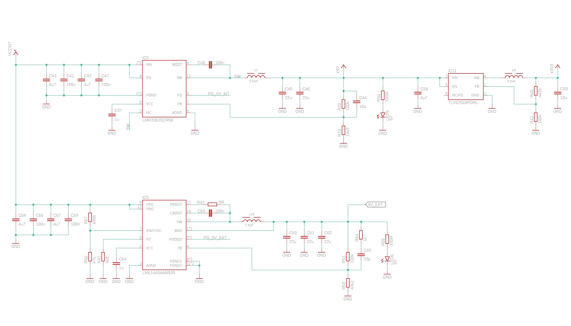
The board is supplied with a voltage of 24V (nominal). My current concept of power supply is shown in the following diagram.


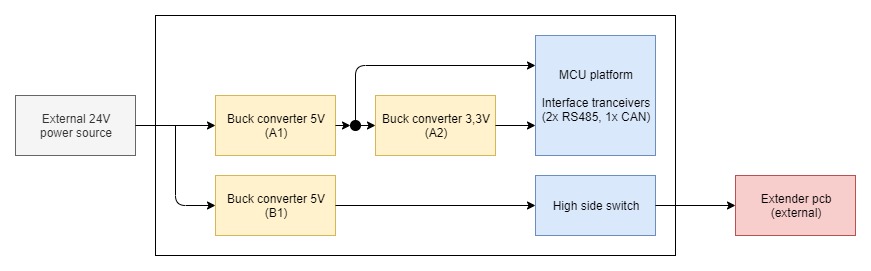
I currently selected the LMR23615 for the internal 24V to 5V power supply and for the conversion from 5V to 3.3V I focus on the TLV62568 (buck converter A1 and A2). For the power supply of the extender board I planned to use a seperate buck converter. The power supply must be implemented in a very space-saving manner (small common footprints and only ceramic capacitors).

My questions:

In general, is the design conception of the power supply reasonable and practical for this application?

Is the LMR23615 a good choice for this application?

Can the second buck converter be used behind the LMR23615 or would another buck converter be more suitable for this design? Would it be better to replace the buck converter A2 with an LDO?

Which switching regulator can you recommend for converter B1 for this application? Currently I have the LM76005 in the immediate selection. I researched the TPS22954 as a load switch. Would this be a sensible choice for the application to switch 5V / 3A permanently? What are the thermal requirements for the TPS22954?

Thank you for your help!

  • Hello

    I think that you plan is OK.

    The LMR23615 is good.

    Of course we have many newer devices that would also work.

    You could look at the LMR33620/30 family or the LM63615/25/35 family.

    These are available in small packages.

    I think A2 is OK to be a buck and is OK to be powered from A1.

    For B1 I would look at the two families I just mentioned.

    We have calculator tools on our website for most of these devices to 

    help with the design.

    We are also happy to review your final design schematics and PCB layout when ready.

    Thanks

  • Hello,

    thank you for your reply! For Buck converter A1, the LMR33620 seems to be a good alternative to the LMR23615. With the LMR33620, the space requirement on the board will probably be less. For buck converter A2, i focused again on the TLV62568 or TLV62568A. Is this a good choice in this setup?

    During my research I came across the reference design PMP15039. Would a similar space-saving design be possible with the LMR33620 and the TLV62568 / A?

    For buck converter B1 i will have a look on the LM63635. One requirement for the power supply of the extender board is that it can be switched off (power sequence, power saving mode). Can the enable function of buck converter B1 be used for this or is it more recommended to use a load switch behind B1 (for example TPS22953 / TPS22954)?

    Thank you for your help!

  • Hello

    Yes, I think that the TLVxx devices you mention are OK.

    Yes, you can do something like what is shown in the PMP15039 design.  Keep in mind that

    thermals become important with such a small PCB; notice the thermal images in that document.

    You can use the EN control to shut off the LM63635.  However, you will need to consider what kind

    off-board "load" the device will see.  If there is a chance that the load could try to back-feed to the 

    regulator, then you may need a switch.  Also, if there is a large capacitance to charge up, it may be best

    to start the regulator and then turn on the switch.  The switch may also be needed for true isolation.

    In any case a transient suppressor on the output of the regulator may be prudent, when the output is taken

    to the outside world.

    Thanks

  • Hello,

    thank you for your reply. I had a look on the LM63635 for buck converter B1: The HTSSOP package is a little bit to big for our design. Unfortunately, we only have limited space on the pcb for the buck converter.

    Furthermore, I now have more specific information about the current consumption of the extender board: The extender board (cellular module) requires around 125 mA in normal operation (receive mode). If data is actively sent via the extender board, the current consumption is temporarily around 3A. The LM63635 can deliver a maximum of 3.25A. Would a more powerful buck converter be recommended?

    After further research, I came across the LM76003 with a maximum of 3.5A in the WQFN package. Would this be a sensible choice for the application?

    Thank you for your help!

  • Hello

    I think that either the LM63635 or the LM76003 would be OK.

    The LM63635 is also available in the WSON package.

    Thanks

  • Hello,

    after some more research i fixed the choice using the LMR33620 for buck converter A1 and the LM61440 for buck converter B1. Within these bucks i got a good compromise for the power requirements and the pcb size.

    Can you please have a look on my schematic: I use the LMR33620CRNX (2100 kHz) and the LM61440 with a switching frequency nearly 2100 kHz.

    For the design i got these questions:

    (1) For the LMR33620 output filter i found different typically values. Is it more recommended to use 4x 22uF on the output filter?

    (2) In the most evaluation designs are capacity packages 1210 or 1206 used for the input and output filter. Can smaller capacity packages (0805) be used in the design? What is in general recommended?

  • Hello

    Your schematics look reasonable. 

    It is best to check both using the spreadsheet design tools on the product folder for these devices.

    For the LM33620 at 2100kHz, then 2x22uF is OK.

    We like to use 1206 or 1210 since they hold their value with DC bias better then the small case sizes.

    You can use 0805.  Be sure they are a good dielectric such as X7R.  And check the DC bias de-rating.

    Thanks

  • Hello,

    thank you for your reply! Another consideration is to reduce the power setup to use only the LM61440 for 24 volt to 5 volt conversion and behind the TLV62568 for 3,3 volt to power our board and the extender board from the LM61440. The extender board (cellular module) causes enormous load jumps while data is being sent (3A). Would it be advisable to supply both - our circuit board and the extender board - from the LM61440? Can the LM61440 handle these load jumps?

    Thank you for your help!

  • Hello

    I think what you have now is better for isolation.

    The regulator can handle the current jumps, with some amount of transient on the output.

    More output capacitance could be added to help reduce the transient.

    As I mentioned I think what you have is OK.  Maybe the next gen you can try to 

    reduce the number of regulators :)

    You can also get the TI EVM for these devices and test in the lab to help with

    your plan.

    Thanks