This thread has been locked.

If you have a related question, please click the "Ask a related question" button in the top right corner. The newly created question will be automatically linked to this question.

LMG1025-Q1EVM: Questions about LMG1025 output waveform

Part Number: LMG1025-Q1EVM

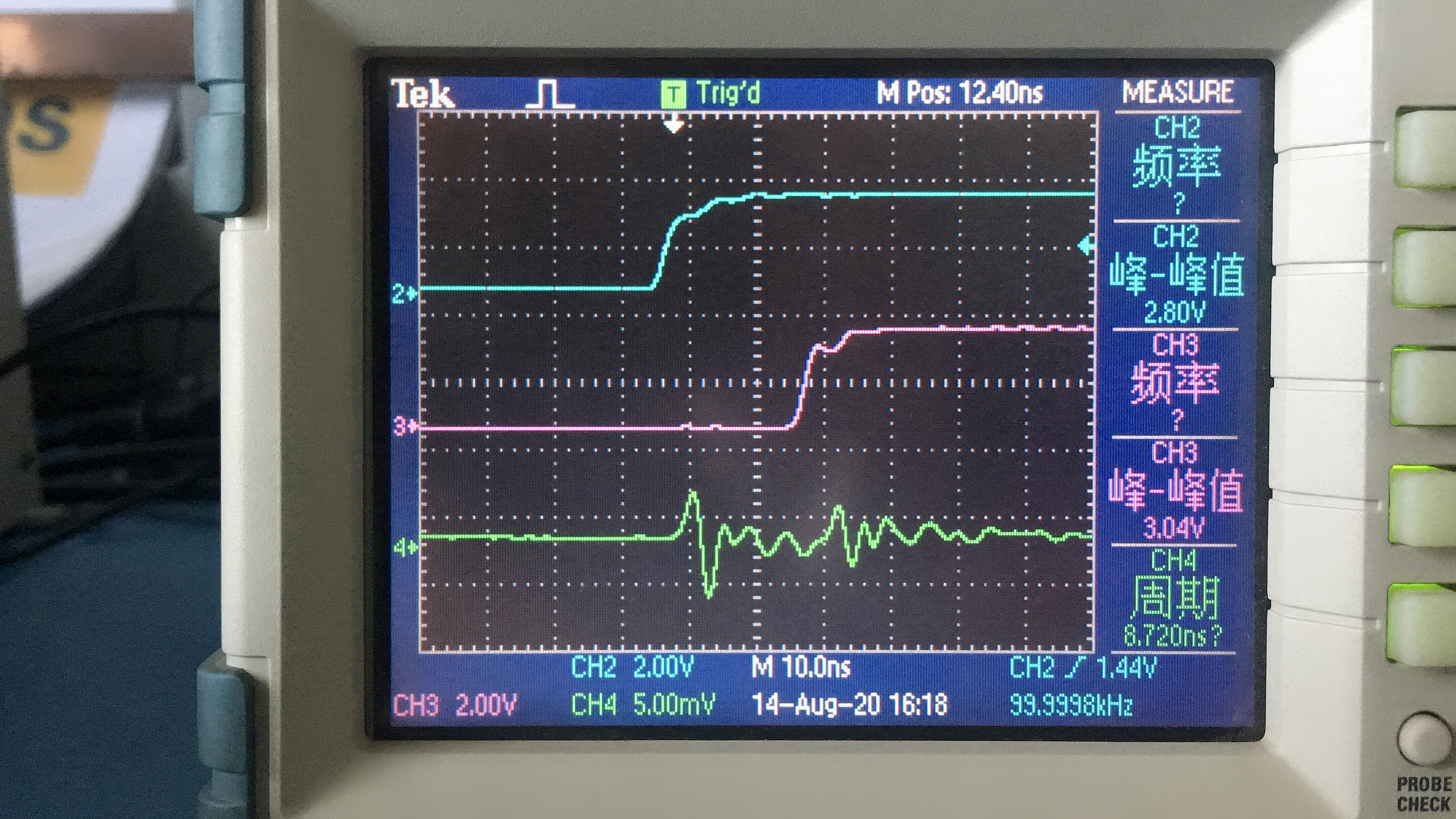
In my current test, I input two 100KHz signals into LMK1025EVM, and I have adjusted the phase difference to the maximum.

Why is the output waveform of LMG1025EVM at Vg not as ideal as the simulated waveform on the datasheet?


My TICS Pro software configuration is as follows.

TICS Pro configuration.pdf

  • Hello Jiao,

    Thanks for reaching out.

    I am not sure I understand the question. I understand you're trying to replicate FIgure 10 from the EVM user's guide, can you please clarify the waveforms on your picture ch-3, ch-2(blue) and ch-4(green) measurements. Is ch-4 (green)suppose to be the gate signal? please confirm.

    I also assume you have not made any modification to the EVM. If not, please confirm modifications made to initial EVM out of box. 

    Regards,

    -Mamadou

  • Hi Mamadou,

    The blue waveform is the two input signals of 100KHz, and the green line is the output signal at Vg.

    And I only removed the resistor R11.

    Regard,

    -Xinhang

  • Xinhang,

    This issue could be related to several factors including measurement probes, we recommend tip & barrel method with short ground leads to minimize stray inductance as this can compromise the gate drive signal. Ensure that you're capturing waveforms as shown on Figure 7 of the users' guide.

    Once you have the correct measurement technique and you're still seeing similar gate waveform, please place R11 back to configure the EVM as from out of box to recapture waveforms. This will confirm whether the IC is still normal or if it is damaged.

    Please let us know then if you're still having issues for further debug.

    Regards,

    -Mamadou