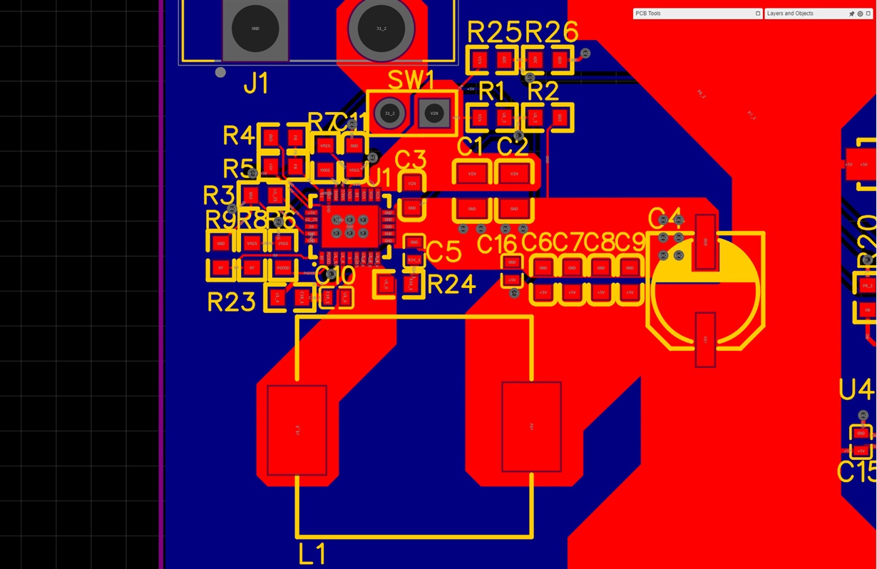
Hello, I am laying out a board that includes a TPS53515 IC to step down voltage from a lithium ion battery to 5V for a microcontroller and some addressable LED strips. I would greatly appreciate feedback on my layout before I send the board to be manufactured. Keep in mind that I am hand soldering and this is a small prototype batch.
Some info:
SW1 will not be populated with a 0.1 header but rather with 2 thick copper wires which will be soldered to a rocker switch. There should be no concern with current handling capability of this setup.
I followed the schematic given by WEBENCH, however, that schematic did not include a 3 ohm resistor on the VBST pin. Is this resistor necessary? Another thread here suggests that it is.
Is the snubber circuit between SW and PGND necessary if the layout is done right?
I have included pictures of the schematic and PCB layout.
Best regards,
Daniel


