Hello,
We are developing a full bridge three phase active recitifier where we implemented your UCC5390E gate driver. The rectifier is designed in a way that the driver circuits are located on separate PCBs (one PCB per driver) and the Driver Card PCBs are stacked on the main power board where the MOSFETs are located (Cree C3M0120090D). For the dual output supply we are using Recom R12P21503D DC/DC converters. Some of the main design characteristics of our driver card are:
- IN- tied to ground
- VCC2 = +15V, VEE2 = -3V
- VCC1 = 3V3 (but we tried also 5V and 12V)
- Air gap placed on the PCB bellow the driver and DC/DC for galvanic isolation
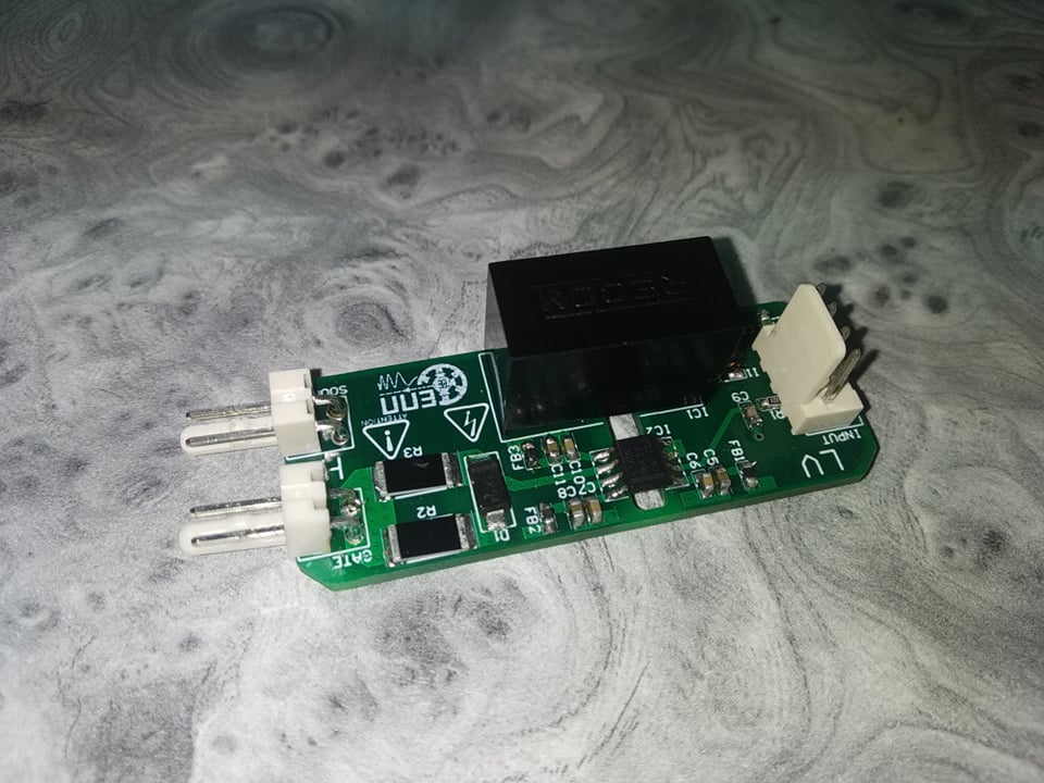
In the attached file is the schematic photo of the driver circuit, photos of the assembled Driver Cards and Altium project files for the Driver Card.
So far we have assembled 2 out of 8 driver cards and none of them are functioning. To be precise, all supply voltages are coming to their adequate pins (VCC1, VCC2 and VEE2). Also we measured that the IN+ signal is commingIn all situations the output pin is pulled to VEE2. We tried several things so far:
- Checking that the assembly is done correctly (that the placed components on the board are the same as those in the schematic.
- The output of the DC/DC is around +16V and -3.5V respecively for the VCC2 and VEE2 pins. The voltages were measured as said before directly on the driver IC pins.
- All solders are okay and that the PCB manufacturing corresponds to the design files.
- Tried measuring the output while the output pin is left floating, 150R resistor connected between the gate and source and we also tried with the original MOSFET that the driver is designed to control
- Powering the VCC1 with 3V3, 5V and 12V. The IN+ was on the same voltage level.
- Disconnecting the DC/DC and connecting an external dual output supply to the driver.
- We tried bringing a constant high signal on the IN+ instead of a PWM signal.
- We tried switching to a unipolar supply by disconnecting the -3V and connecting the VEE2 to GND2 (SOURCE pin that is).
In the design and test phase we deeply studies your materials relating the UCC53x0 series drivers, such as:
https://www.ti.com/lit/ug/sllu238/sllu238.pdf?ts=1598528662379
TI E2E support forum regarding issues with this driver series.
Do you have any suggestions what is the issue so far? The design of the driver circuit is relatively simple but we cannot understand why this driver does not work.
Regards,
Nenad Djalovic