This thread has been locked.

If you have a related question, please click the "Ask a related question" button in the top right corner. The newly created question will be automatically linked to this question.

WEBENCH® Tools/LM2842-Q1: Bode Plot (Gain-Margin)

Part Number: LM2842-Q1
Other Parts Discussed in Thread: LM2842

Tool/software: WEBENCH® Design Tools

I have a question regarding the stability simulation and analysis of the LM2842.

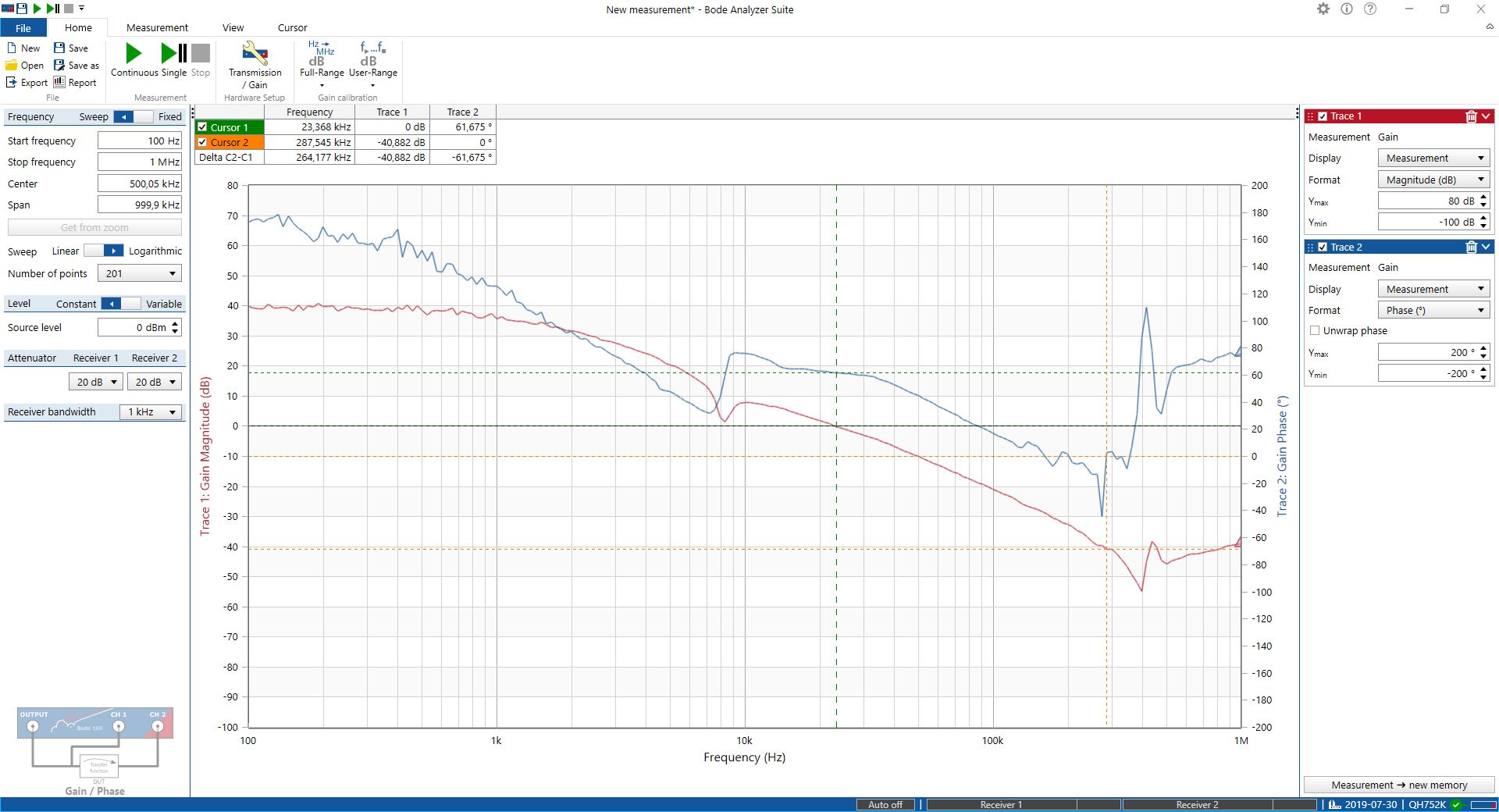
Simulated with Webbench the Bodeplot give a phase marging (0db) of ~60°. But there is no gain margin given because these phase never reaches 0°. [see picture at the end]

The configuration i took from the evaluation board.

We build different cofigurations (12V -> 5V)/(5V -> 3V3)/(5V -> 1V2) but nearly all have at different load points the problem that the phase does not reaches 0°. Measurement was done with the Bode 100.

In my understanding it is essential for the stability to have a phase marging (0db) of >45° and a gain marging (0°) of ~20db. It there an explenation why its not possible to reach 0° and why thats okey with that configuration?

Thank you for your help

Alexander Fitzner

  • Hi 

    cause used large output capacitor, the internal zero is far from the system pole, so the cross frequency and phase is low. and when frequency high, the internal zero with ESR zero boost the phase make the phase keep higher than 0. I think you may need test to very high frequency , then the phase will go below 0

    but I think the system is stable. in practical design  , phase margin high than 30 will be a stable system. and for  gain margin, it is for avoid the negative feedback loop become postive feedback which need phase cross 0 , the gain margin need to be negative. the phase higher than 0 from 100 to 1Mhz means in these frequency range, it is all negative feedback.

    thanks

  • Hi,

    thank you for your fast response.

    Ok thats means i dont have do worry about it, thats good to know.

    Maybe one more question:

    I did measurements on a real circuit (5V to 3V3) with the Bode 100 [see picture a the end].

    It seems like i have a resonance frequeny at about 7 to 9 kHz where the phase and the gain have a jump. In these test the ciruit has just a resitive load of 8 Ohm ~410mA.

    Do you have a recommandation how do deal with that behaviour, because when the bode 100 sweeps over that point i see a change in the input current (~40mA) and you are able to hear the rinning of the inductor (a guess of mine).

  • Hi

    do you have input filter in the circuit?

    Thanks