This thread has been locked.

If you have a related question, please click the "Ask a related question" button in the top right corner. The newly created question will be automatically linked to this question.

TLV742P: Simulation when the output is connected to the Load Switch output

Part Number: TLV742P

Hi,

I am simulating about a circuit using LTSPICE. TLV74218P and TPS22914C netlists were imported into LTSPICE.
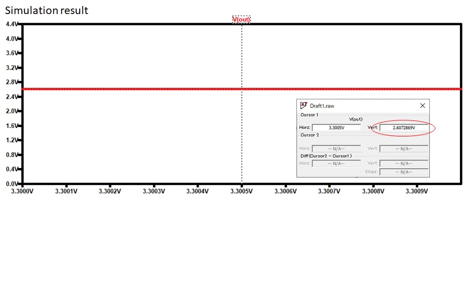
Looking at the simulation result, V(out) is 2.607V,but correct value should be 3.3V(The output of TLV74218P should be off)
Would you tell me this cause?

Regards.

  • Hello,

    Unfortunately TI cannot support LTSpice due to its EULA, which prohibits the competitors of ADI/LT (such as TI) from using LTSpice to promote their products.

    On first glance it appears that there could be an issue with the output of both devices connected directly together. The LDO output will want to produce 1.8V but the load switch output will want to pass Vin, which is 3.3V.

    Unfortunately due to the EULA, I'm unable to assist any further with this debug.  I would recommend using Cadence PSPICE, which you can use for free by going to this link.

    www.ti.com/.../PSPICE-FOR-TI

    Thanks,

    - Stephen