This thread has been locked.

If you have a related question, please click the "Ask a related question" button in the top right corner. The newly created question will be automatically linked to this question.

BQ2000T: Switching frequency formula doesn't appear to match actual device performance

Part Number: BQ2000T
Other Parts Discussed in Thread: BQ2000, BQ2000EVM

Hello,

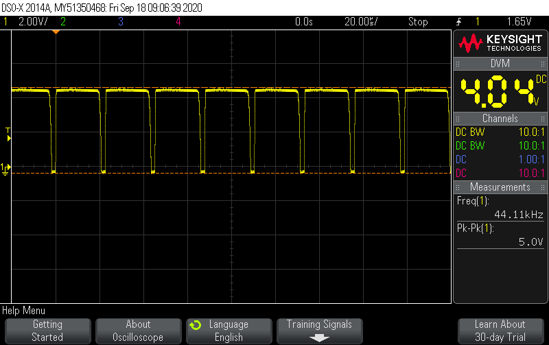
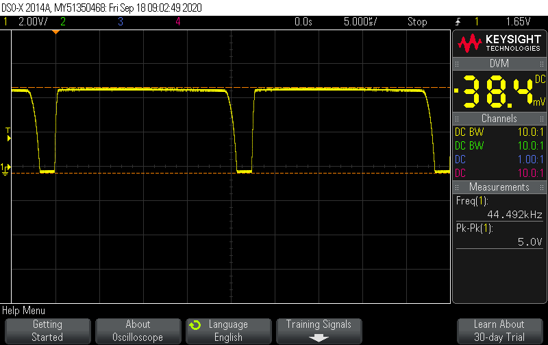
In the document "Using the bq2000/T to Control Fast Charge" there is a formula on page 4 for maximum switching frequency: Rf * Cf = 1 / (4 * F).  When I look at the values for Rf and Cf on the bq2000EVM, I see 604 ohms and 1000 pF.  That translates to a max. frequency of 414 kHz.  This well exceeds the recommended range of 100 to 200 kHz.  On the bench, I'm seeing a max. of 130 kHz from the EVM, at 50% duty cycle as predicted.  Is the formula incorrect, or is something else going on?

Thanks,
Scott

  • Hi Scott,

     Do you have a waveform of the switching frequency? The Rf and Cf values have the most effect on switching frequency, but it is affected also by the input voltage, RSNS value, inductor value, hysteresis capacitor value (CHYS) as well. 

    Figure 9. and 10. of the datasheet show empirical data as well. Datasheet: www.ti.com/.../slus149d.pdf

  • Hi Kedar,

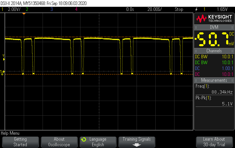
    So I appears that the formula is less accurate, and the graphs (Figs. 9 & 10) are better.  I've attached images of the switching waveform, at the junction of the FET and inductor.

    Side question: one of the three images shows the switching waveform when the wires to the battery are really long, such as when we're using a meter to measure battery current.  What causes the pauses between pairs of pulses?

    Thanks,
    Scott

  • Hi Scott,

       The pauses are when the freewheeling body diode is conducting. As this is a switching converter, the HSFET (PFET) will conduct for a portion of the duty cycle, during which the SW node will be high, and for the other portion of the duty cycle, the diode will conduct with GND as the source. As the switching frequency is slower in this part, and there is no remote BATSNS, the extra voltage drop caused when the HSFET (PFET) is on will cause a noticeable voltage drop between real battery and where BAT is sensed on the IC. This causes fluctuation which will affect the sensed voltage, and will affect the duty cycle.

  • So it's the additional voltage drop caused by the long cables which extends the time gap?  Why are there pairs of pulses between the gaps instead of just single pulses?

  • Hi Scott,

       As the switching frequency is low:

    • There is a voltage drop when PFET is on, across your cables. The moment the PFET needs to turn off, then there will be a voltage drop as the inductor current ramps down (inductor current waveform is sawtooth). As the voltage at the output of the converter is fluctuating, it is hard for the converter to regulate and maintain stable duty cycle. I would not recommend this test setup with long cables.