This thread has been locked.

If you have a related question, please click the "Ask a related question" button in the top right corner. The newly created question will be automatically linked to this question.

TL494: push-pull converter unstable output voltage

Part Number: TL494
Other Parts Discussed in Thread: UCC27324, TL431

Hi,

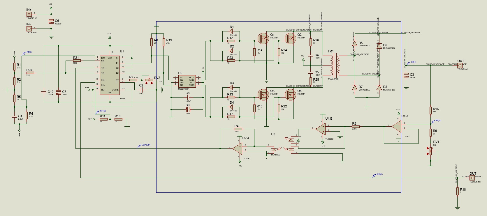
I have been working with TL494 recently for my bachelor project at university. I have designed a push-pull converter which boosts up 12VDC to 340VDC after rectification. The problem that I faced is that the output voltage drops significantly when I add load to the circuit. For example, if the load pulls 100 ma, the output voltage drops 310V from 340V. if the load pulls 200ma, it drops to 270V. I have used electronic loads and resistive load, it gives me the same results. The design is vital for my project. So, I would really appreciate your help.

Kind Regards  

  • Hi Murat

    I believe your regulation problem is related to lack of current in the optocoupler. Here are a few comments/suggestions:

    1. U4:A-1 is VOUT (OUT+) divided down by R16, R9 and RV1. RV1 is a 20k potentiometer. Assuming you are trying to maintain OUT+=340V, the output of the U4:A buffer will vary by 1.7V<U4:A-1<8.3V. Consider this to be your control voltage range for the optocoupler.
    2. The maximum VF of the Opto LED is 1.9V. U3-4 is GND and this is the anode of the LED opto you are trying to control. The only way this LED opto can conduct is when the voltage at U4:B-6 is <-1.9V which can never happen.
    3. The other LED opto has 12V on the anode (U3-2) and U4:B-7 on the cathode. U4:B is almost infinite gain (by the op amp open loop gain) so any voltage greater than GND on U4:B-6 will drive U4:B-7 to GND. The LED opto U3:1-2 is fully on all the time and this means the opto feedback does not respond at all to changes in +OUT. Any load placed on +VOUT will cause +OUT to decrease.
    4. Reconfigure the opto coupler so that it is responding to the changes in +OUT
    5. Measure the feedback voltage going back to the TL494 to verify the opto curreent is reponding to the changes in +OUT. 
    6. Did you intend for the second opto LED to be on? If not, make sure the second opto LED is OFF. Force it to always be OFF because I believe it is always fully ON and this is saturating the TL494 feedback voltage. Connect U4:B-2 to GND and reconfigure the op amp so that U4:B-7 is >0V always.
    7. Make sure you have enough opto current through the LED diode according to the expected control voltage range. 330k resistors are too big....the usual expected value is something in the range of hundreds of ohms to a couple k-ohms

    Good luck on your project,

    Steve M

  • Hi Steve,

    First of all, thank you for your swift reply. I have just removed the op amps and optocoupler. I feed the pin1 through voltage divider. I still have the same problem.

    *** I have just noticed that once I add load to the circuit,12V on TL494 and UCC27324P drops down to 5V or less. I used  almost a meter long cable which is around 1 - 1.5 ohm and the voltage significantly drops before it reaches to my circuit. I didn't put into account that the cable might be the problem. To solve the problem, I increased the input from my power supply to keep 12V input voltage stable which seems to work fine even it's as less as 10V. Thank you very much for your support and TI family.

    Best Regards
    Murat

  • Murat

    If you remove the op amps and opto and drive pin 1 directly (through divider) you are operating the converter open loop and the error amp has high gain (~200). If you are going to drive pin 1 this way, you should first reduce the gain by changing R21 from 100k to 510-ohms. This is not a solution to your feedback problem but you should at least see the duty cycle varying when you change the voltage on pin1 with a fixed input voltage. Maybe the reason you saw no duty cycle change was because the error amp is saturated due to the high DC gain - is the error amp output voltage changing when you change the pin 1 voltage - if not, it's saturated?

    About the 12V dropping to 5V - how are you providing bias to the TL494 and UCC27324? Is it from a lab bench power supply that might be in current limit?

    Your entire feedback network from the +OUT divider to the error amp input needs to be redesigned properly. I believe all the components are in place (op amps and opto) but you need help configuring the feedback. Many design resources are available that use the popular TL431+opto feedback. The TL431 can only sink current but you would be replacing the TL431 with your op amp which can source current. 

    Also, you mentioned you were trying to load +OUT=340V with 200mA. This is 68W - what is your intended output power when the converter is working properly? Why do you have no inductor on the converter output? As you increase output current, the AC ripple voltage seen at +OUTis going through your op amps and if the opto were working properly, this AC ripple voltage would be seen at the error amp input. What is the output voltage ripple without an output inductor? 

    Regards,

    Steve M

  • Hi Steve,

    I will work on doing a new design. I designed this for a quick test. You are right I am missing an inductor. I have noticed it little bit late. Intended output power is 300w. Sorry for lack of knowledge. How do you calculate the gain? And what does it refer to? So my problem so far seems to be input cable! Voltage drops on 1 ohm cable before it reaches to input terminal. I am going to use smaller cable next time.

    Regards