This thread has been locked.

If you have a related question, please click the "Ask a related question" button in the top right corner. The newly created question will be automatically linked to this question.

TPS7A52: Please validate my schematic design.

Part Number: TPS7A52

Hi Team

I created a 3.3V output Schematic with TPS7A52.
I have inserted a File, so please check it and comment.Sep_17_TPS7A52_3.3V_2A_Design_File_Shintomi.pdf
Regards,
Yuichi Shintomi
  • Hi Yuichi,

    A few comments:

    For output accuracy (4-1), the TPS7A52 accuracy spec already includes the line and load regulation since the spec is across the entire range for Vin and Vout. So you just need to add your resistor divider error to get the total accuracy. 

    For dropout (4-2), the minimum headroom that the application will have will be Vin(min)-Vout(max)=3.6*0.9817-3.3*1.0075=209.4mV (which is more than the max dropout of 170mV listed in the PDS which is good). 

    For Tj (4-3), the max drop across the LDO is the 409mV you calculated, and the Tj you caluclated is correct based on the JEDEC standard board. You can likely get better with a real PCB layout but at the current 84C you are at a reasonable max temperature since this device is specified up to 125C. 

    The schematic doesn't show the schematic for the TPS7A52, so I wasn't able to review the schematic to check min/max Cin, Cout and the resistor divider values. If that is needed please follow up. 

  • Hi Kyle

    Thank you for your kind reply. Also, I apologize for the mistake in the circuit & BOM materials. I will send you the corrected file.
    I understand the TPS7A52 accuracy spec already includes the line and load regulation. Thank you.
    For dropout (4-2), I was relieved by your reply.
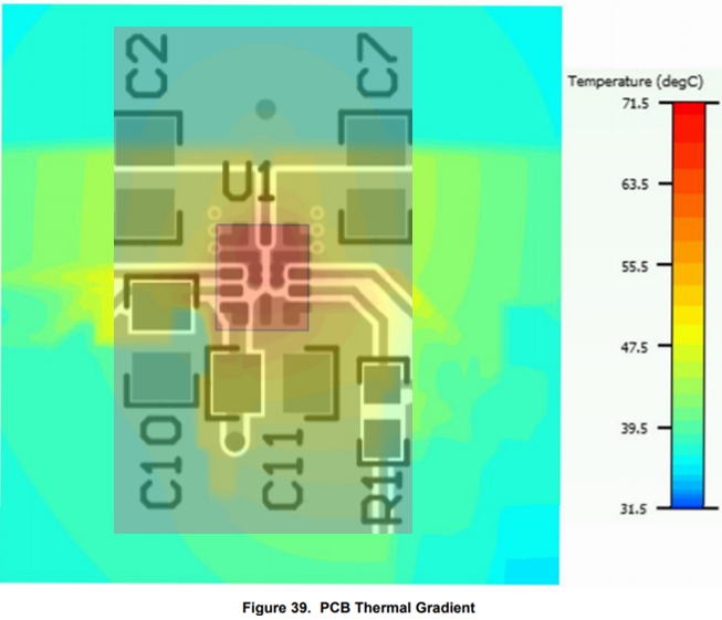
    For Tj (4-3), I also speculate that it will go down in the actual PCB. We are designing at the worst. MLCC uses 85 ℃ parts, but if you look at P28 "Figure 39. PCB Thermal Gradient" of Datasheet, I think that there is no problem with 85 ℃ parts. Is this idea correct?
    Regards,
    Yuichi Shintomi
  • Hi Kyle

    Thank you for your quick reply.
    My point is that the heat generated by the LDO does not cause the ambient temperature to exceed 85 ° C. If the ambient temperature rises to 85 ° C due to the heat generated by the LDO, it will exceed the MLCC (85 ° C max) rating. I think that Fig. 39 is probably okay from 1W, Ta = 25 ℃, but I am wondering how to judge because the circuit diagram uses Bias voltage. I'm not using Bias voltage.
    Regards,
    Yuichi Shintomi
  • Hi Yuichi,

    I don't see any problems with the schematic, though I have think it would be good to evaluate the inrush current just to make sure your system doesn't have any startup concerns due to the amount of output capacitance. 

    • I see that there is a large amount of capacitance on the output of the LDO (~225uF), this isn't a problem for the LDO however you may want to verify that the input supply will be able to supply the needed current to charge up all those claps without causing the input voltage to droop too much. 
      • Below is a screen shot of the startup time equation and EC table showing the charging current. The highest inrush current will occur when Inr/ss is largest so using the max value will provide the a worst case so tss=Vnr*Cnr/Inr=(0.8V*10nF)/10uA=800us. Then we can use I=C*dV/dt to estimate the inrush current needed at startup so I=225uF*3.3V/800us=0.928A. If we assume a +20% tolerance on the output caps and a -20% tolerance on Cnr/ss then I=1.392A. 
        • Again this is not a concern for the LDO itself, just make sure the input supply is capable of supplying this with any other loads on the 3.6V rail. Additional input capacitance could be used if needed to help provide additional charge but it doesn't seem like it'll be needed so I'm noting it just in case there are system other considerations I'm unaware of. 
        • If needed another option to reduce inrush current would be to increase Cnr/ss to further slow down the ramp but it doesn't seem like it'll be needed.

  • Hi Yuichi,

    Whether you use Bias or not will not have any effect on the thermal dissipation of the LDO. Almost all of the thermal dissipation occurs due to the current flowing from Vin to Vout (though the resistance of the pass device). At full load the power dissipation due to the ground current is only bout 3-4% of the total power dissipation. 

    I don't think the LDO itself could heat the ambient air enough to cause a significant increase in the ambient temperature. If you have 2A flowing through the LDO and only 300mV from Vin to Vout, you're only talking about a power dissipation of 0.6W. The downstream loads would be consuming 2A at 3.3V which is 6.6W and their thermal dissipation should dominate the heating of the ambient air compared to LDO.

    Assuming you have an enclosure around your system, you'd need to do a thermal simulation of your whole system to determine the ambient temperature when the system is running. 

  • Hi Kyle

    Let me check first.
    There are TPS7A52 and TPS7A52-Q1. I use TPS7A52.
    Thank you.

    Regards,

    Yuichi

  • Hi Yuichi,

    Sorry for the confusion, I was evaluation the schematic looking at the automotive version of the TPS7A52. I've amended my removing the question about GND and NC pins. 

    As for the thermals,I better understand your request about Figure 39 and of the LDO heating up the capacitors. As you mentioned the EVM shows that the heating isn't very much but below I've overlaid them so you can get a sense of where the capacitors are in the heat map. The PCB around the input and output caps are likely ~45C, while the PCB around the Bias cap is likely ~49C (though as you mentioned you are not using this capacitor). The other components will be significantly cooler. 

  • Hi Kyle

    Thank you for your kind reply. I was relieved at the temperature. Check the inrush current for the entire power supply system. Currently, it is in the unit design stage, so we will proceed with the circuit presented.
    Are there any other issues?

    Regards,

    Yuichi

  • Hi Yuichi,

    No, I do not see any other issues or concerns.

  • Hi Kyle,

    Thank you for your kind reply. The point of inrush current was nice to remind me that I had forgotten.

    Regards,

    Yuichi