This thread has been locked.

If you have a related question, please click the "Ask a related question" button in the top right corner. The newly created question will be automatically linked to this question.

LMR33620: Encountering an oscillation and the LMR33620 cannot provide a stable 5V output

Part Number: LMR33620

Hello,


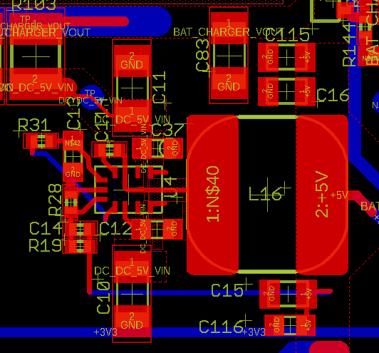
We have a concern about the LMR33620BRNX, a synchronous voltage controller. We followed your recommendations for the electrical design in order to obtain an output voltage of 5V. You will find attached the electrical design (dcdc_schematic.png).


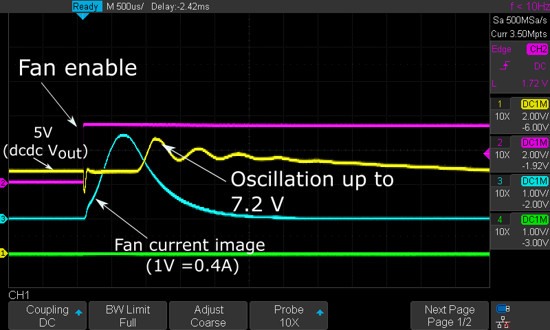
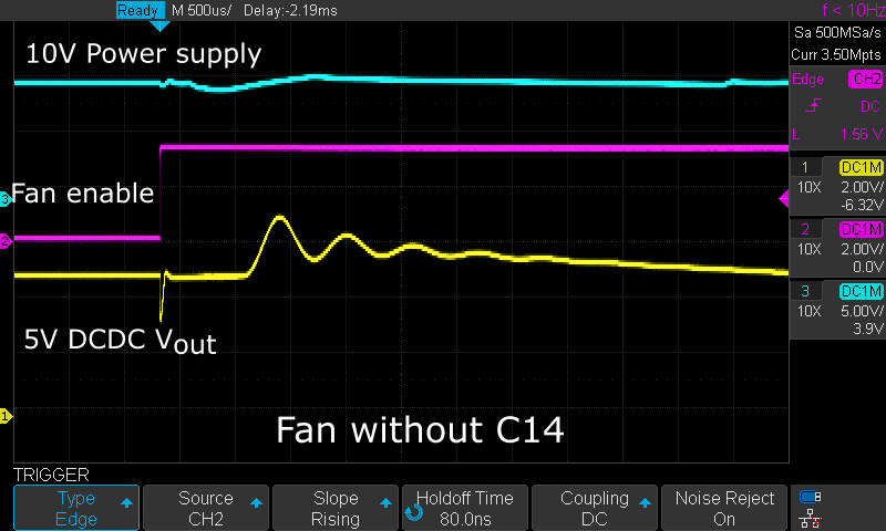
This voltage controller is used, to power a fan among others peripherals, (please find attached the electrical design in fan_schematic.png). The power on/off of the fan is controlled with a IO (MCU_FAN_EN in the schematic). The problem is when the fan is switched on, oscillations are noticed on the 5V, with a peak at about 7.2V. The current draw during fan start-up is about 1A (signals are shown in osc_signals.png attached). This unexpected voltage peak may damage our others peripherals that are powered by this controller, so we need to understand where does it come from.


Do you have an explanation for these oscillations, and why the voltage regulator cannot maintain 5V during the fan startup. Do you have any recommendations on how to prevent these oscillations?


Thanks for your help.


Best regards,

  • Hello

    What is the input voltage during this test?

    Can you put a scope probe on the input and make sure it is clean.

    What is the peak fan current; it is hard to read.

    Can you test with a resistor or Eload and see if it is OK; without the fan load.

    Can you temporarily remove C14 and test again.

    Please send a snapshot of your PCB layout.

    Thanks

  • Hello,

    Thanks a lot for your quick response ! So here are the answers to your questions :

    - The input voltage is a 10V power supply. I put a scope probe on it (blue signal).

    - The peak fan current is around 1A.

    - Indeed, we have the same problem with a resistor (see signals below). I try with 1kOhm, so the fan is not the problem... Maybe the fan filter (L4 and C61) ?

    - Removing C14 didn't change anything.

    - Please find two snapshots of our PCB Layout.

    Do you have any ideas ?

    Thanks for your help !

  • Hello

    Your layout is not too bad.  The only thing I would say is to avoid using thermal reliefs on the power components.

    It is possible that the fan filter is causing some issues.  I would try to remove L4 and/or C61 and test with R load

    Then with fan load if the R load looks OK.

    Thanks

  • Hello,

    Removing L4 and C61 solves the problem. So we need to work with another fan filter.

    Nevertheless, we still have a voltage drop that can be seen in all screenshoots. It can be corrected by adding a soft start, connecting C58 and R89 but we are surprised that the voltage controller can't manage the current peak (it is only 5 mA for the 1k Load).

    Thanks for your  help.

  • Hello

    I think that soft-start on the switch is a good plan.

    Thanks