This thread has been locked.

If you have a related question, please click the "Ask a related question" button in the top right corner. The newly created question will be automatically linked to this question.

TPS61175: What will happen when Input voltage is greater than output voltage( for required voltage)

Part Number: TPS61175

Hello I am using TPS61175PWP for boosting voltage from 9-13 V to 12 V. 

The input voltage is taken from PV panel which can vary from 9 V to 13 V.

The required output voltage is 12 V. 

We are using  Typical application circuit provided in product datasheet. Circuit is attached.

My question is when the input voltage is greater than 12 V ( suppose 13V) then this circuit works as buck circuit to regulate input 13 V to 12 Output?  Or this circuit can not provide constant 12 V with variable input voltage?

Waiting for kind reply. Thanks 

  • Hello Imran,

    It seems that the attaching of the circuit did not work. Please attach again.

    Let me answer your question for a general circuit with TPS61175:
    If the input voltage is higher than the output voltage, there is a direct path from VIN to VOUT through the inductor and the diode. So the output voltage will rise to the input voltage minus the voltage drops in the inductor and diode.

  • Hello ,

    I am sorry but I can not understand why attaching never works even I am following instructions for attaching it. I  Will try once again.

    Anyway my confusion is not removed yet. Let me clarify my question.

    We have set R1 and R2 resistor to get 12 V output when input voltage is less than 12 V. This is done by boost function of circuit. Now when if voltage at input is greater than 12 V still it need to work  boost function and increase voltage greater than 12 lets say 15 V, or 18 V I don't know.

    What I understood from your reply is that when input voltage is greater than 12 V( output voltage  for which R1 and R2 are set ) then circuit will not do boost function but there will be direct path from Vin to Vout through inductor and diode. Is that so ? and why and how ? The internal switch (mosfet) stops turn ON and OFF when input is higher than required output?  waiting for your  kind reply. Thanks


  • Hello Imran,

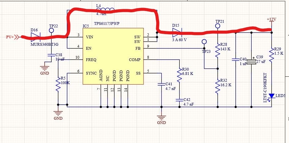
    Please have a look at the red marked path in your schematic here:

    As soon as the output voltage gets higher than the regulated output voltage ( defined by the resistor divider R28 and R32 in your case), the converter will stop switching and doing nothing.

    Now if the input voltage gets higher than the regulated output voltage plus the voltage drops on the 2 diodes and the inductor, the output will follow the input voltage. The converter is not able to stop this current, as the converter is not part of this path.

    You would need to cut this path by a switch to stop current from flowing there.