This thread has been locked.

If you have a related question, please click the "Ask a related question" button in the top right corner. The newly created question will be automatically linked to this question.

LM43601: Negative output not functioning

Part Number: LM43601
Other Parts Discussed in Thread: LMR62014

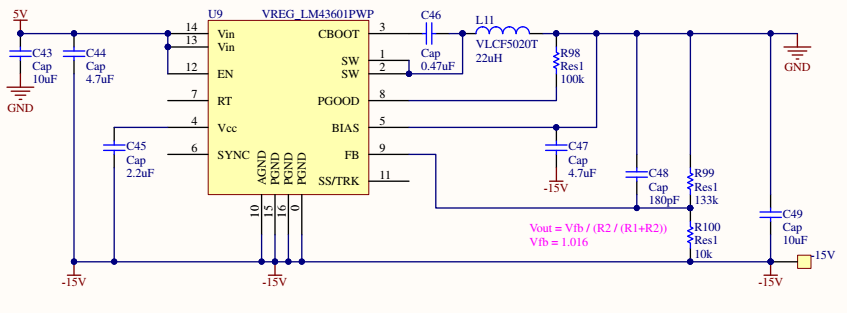
We used a webbench design to setup the LM43601 for 5V input and -15V output at 0.1A.  We are having trouble getting the -15V output to function.

If you manually short circuit from -15Vout to GND for a moment, the output will often start working. 

I saw a post suggesting a 0.47uF soft start cap from pin 11 to -Vout.  This was tried, but did not change anything.

We found that the datasheet (and some other forum posts) say to short the SYNC pin to GND.  We have tried that pin shorted to -Vout, but it did not change anything.

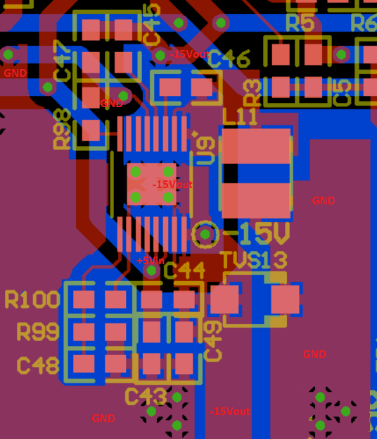
Attached are the schematic and board layout.

Thanks for any help you can provide

  • Hello

    It may be that an input voltage of 5V is too small for this device to boost up to -15V.

    Can you test with an input voltage of 12V.

    Try removing R98.

    Please send waveforms of the switch node and output during bad and good behavior and during start-up.

    What load are you using?  Can you test with no load and see if the output is correct?

    Please check that the input voltage is correct and not dipping or oscillating.  How fast is the input voltage rising?

    Be sure that your output capacitor is rated for at least 25V, so that it will not lose value at 15V.

    You may need more output capacitance.

    Please see the attached application notes for more information.

    You may also get a buck EVM and re-configure and test on the bench.

    PCB LAYOUT:

    You will need much wider traces to the VIN, GND, SW, and BOOT of the device

    Try not to use thermal reliefs on the power components.

    Try to follow the PCB layout in application note SNVA722.

    Thanks

    6685.snva722b.pdf

    7635.snva856a.pdf

  • Thank you for the suggestion list.  We will look into some of these items monday.

    I can say that taking off R98 (PGOOD resistor) had no change.

    The 5Vin is connected to other things on the board  There are some other vregs (+15V swiching, +3.3V linear +3.3V ref), some opamps and a uctrl).  To try a higher input voltage, i cut the Vin trace to this regualator from the 5V bus on the pcb, so i could apply voltage just to this chip.  After doing that, i found that appling the 5Vin to just this chip produced a good -15V output every time.

    I isolated the other things on the 5V bus and found that a +15V LMR62014 regulator on the board is the culprit.
    With the +15V LMR62014 on the same 5Vin bus, the -15V LM43601 regulator doesnt come up.
    With the +15V LMR62014 disconnected from the 5Vin bus, the -15V LM43601 regulator works fine.
    I also found that just holding the *SHDN pin low at startup on the +15V LMR62014 did not help the -15V regulator.

    I have not looked at anything on the scope yet, but something about having both of those regulators start at the same time is causing a problem.

  • Hello

    A few more ideas.  Since the boost will always have some positive output, even when not switching, that voltage

    may be getting to the negative output.  This could happen if there is a common load between the pos and neg output such as 

    an opamp.  You can try a Schottky diode across the negative output as shown in the app note SNVA856.

    Also, you might try a large Al capacitor across the +5V rail near the device; such as 47uF or 100uF as an experiment.

    Thanks

  • The Schottky diode across the negative output to ground seems to work.  Both +15Vout and -15Vout supplies now reliably come up when the 5Vin is applied. 

    Thank you for pointing me to that part in the app note