Other Parts Discussed in Thread: LP2951
Hello,
This is a question relating to Thermal Shutdown of an LP2951-N LDO regulator.
We are trying to debug an issue we have with site failures of a number of our devices. Another manufacturer’s IC is unexpectedly going into a short-duration shutdown mode and then recovering. We think that this may be because of disturbance on the Vcc (+5V0) of the IC, although we are not certain of this.
The Vcc is supplied by an LP2951-N part (markings on the IC are: 3A0J L0DB). Our devices have been in service for 7 years and have only recently failed. The sites where the devices are operated are typically not air-conditioned and ambient could reach +40Deg C, we think. Our devices do not have any forced-air cooling and we estimate that the temperature inside our boxes could get to around 60Deg C.
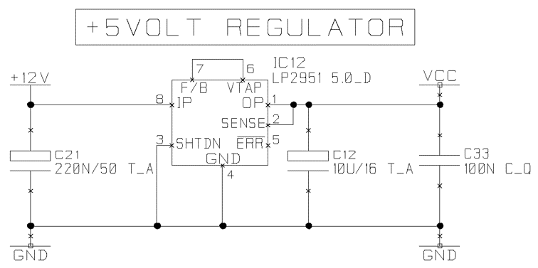
The LP2951 is dropping +12V to +5V0 whilst supplying approximately 65mA. I’ve measured the temperature on top of the package with a K-type thermocouple and the temperature is around 72Deg C. This is at an ambient of about 22Deg C in our office. The board is 4 layer (with internal GND and Power planes) and the LP2951 routing is reasonable. See below for part of our schematic.
I have read the IC Package Thermal Metrics (SPRA953C) app note and think I understand most of it. I have estimated that the Tj could be about 76Deg C using an appropriate equation. I have applied localised heat to the IC using a Steinel HG2310 heat gun set to 60 and 70Deg C at about a distance of 1-2” for a few minutes. I am not sure whether this is valid or not.
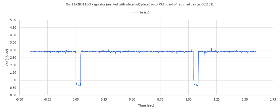
I set our oscilloscope to trigger on a Vcc downward excursion and include the following waveform. See below for the waveform data.
Note that the record length is 5sec. The lowest visible spike is about 3.50V and approx. 5ms wide.
Questions:
- Is 72Deg C typical of what you would expect to measure on the top of the IC for 12V to 5V0 regulation @65mA, ambient being around 22Deg C? I’m wondering if this part is running too hot as it feels very hot to the touch?
- Are my oscilloscope traces showing the thermal shutdown mode in operation, or are we seeing another phenomenon?
- The other manufacturer has said that Vcc dropping to 2V5 might put their part into difficulties and be the cause of our site problems.
- There is scant information about Thermal Shutdown in your datasheets. Could the output go as low as 2V5 or even 0V?
Thanks, and Regards
Mike Ellis

Hello,This is a question relating to Thermal Shutdown of an LP2951-N LDO regulator.We are trying to debug an issue we have with site failures of a number of our devices. Another manufacturer’s IC is unexpectedly going into a short-duration shutdown mode and then recovering. We think that this may be because of disturbance on the Vcc (+5V0) of the IC, although we are not certain of this.The Vcc is supplied by an LP2951-N part (markings on the IC are: 3A0J L0DB). Our devices have been in service for 7 years and have only recently failed. The sites where the devices are operated are typically not air-conditioned and ambient could reach +40Deg C, we think. Our devices do not have any forced-air cooling and we estimate that the temperature inside our boxes could get to around 60Deg C.The LP2951 is dropping +12V to +5V0 whilst supplying approximately 65mA. I’ve measured the temperature on top of the package with a K-type thermocouple and the temperature is around 72Deg C. This is at an ambient of about 22Deg C in our office. The board is 4 layer (with internal GND and Power planes) and the LP2951 routing is reasonable. I have read the IC Package Thermal Metrics (SPRA953C) app note and think I understand most of it. I have estimated that the Tj could be about 76Deg C using an appropriate equation. I have applied localised heat to the IC using a Steinel HG2310 heat gun set to 60 and 70Deg C at about a distance of 1-2” for a few minutes. I am not sure whether this is valid or not. I set our oscilloscope to trigger on a Vcc downward excursion and include the following waveforms: The record length is 5sec. The lowest visible spike is about 3.50V and approx. 5ms wide.Questions:1. Is 72Deg C typical of what you would expect to measure on the top of the IC for 12V to 5V0 regulation @65mA, ambient being around 22Deg C? I’m wondering if this part is running too hot as it feels very hot to the touch?2. Are my oscilloscope traces showing the thermal shutdown mode in operation, or are we seeing another phenomenon?3. The other manufacturer has said that Vcc dropping to 2V5 might put their part into difficulties and be the cause of our site problems.4. There is scant information about Thermal Shutdown in your datasheets. Could the output go as low as 2V5 or even 0V?Thanks, and RegardsMike Ellis