This thread has been locked.

If you have a related question, please click the "Ask a related question" button in the top right corner. The newly created question will be automatically linked to this question.

TL431-Q1: TL431AQDBZR part is getting heat up

Part Number: TL431-Q1
Other Parts Discussed in Thread: TL431

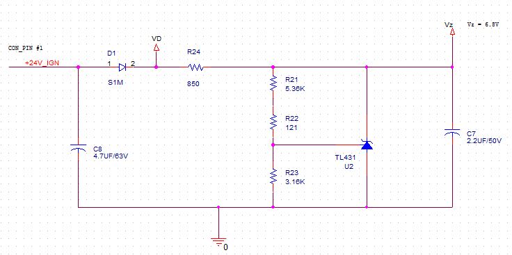
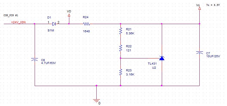
The used device is getting heat-up. Please the used ckt as attached.

Input voltage Typ = 24V +/- 4V

Output voltage Vz= 6.8V

Current flowing through TL431 is approx 25 mA.

Please look into the used ckt and guide us, why the device is getting heat-up.

Regards

VB Singh


  • Hi Vijay,

    Can you show us a higher resolution schematic?

    How much temperature is it heating up above ambient?

    The device is sinking 0.17W which should be around 50C above ambient.

  • Hi Marzoo,

    Please find the attached schematic with higher resolution.

    The device temperature is approx 65 DegC @ 24DegC ambient.

  • Hi Vijay,

    That temperature is expected when the device has to handle 0.17W = 6.8V * 25mA. The RJA thermals is 334.7 C/W. So the TL431 is expected to be around 46C = 334.7C/W * 0.17W above ambient so this is expected behavior.

    I would recommend to use fig 35 linear regulator with the TL431 from the datasheet if you want to use the TL431 for a low cost solution linear regulator that will not get as hot.

  • Hi,

    Ok I understand your view point. We have made the ckt as per Data sheet Figure-28:Shunt Regulator.

    As i understand from datasheet, Ika >/= 1 mA to regulate the Vka Voltage. In my application the load on Vka is approx 1 or 2 mA only.

    I have done one experiment:

    Objective: Reduce the current flow through TL431 from 25 mA, Means reduce the power dissipation. 

    Changed the value of R24 from 825 Ohm to 3 KOhm, Now Current is = (24-6.8)/3 KR= 5.7 mA.  Now the TL431 device temperature is approx 10 DegC is above the ambient.

    This is OK for my application.

    Query: Is it a right approach to reduce the heat of the device? is there any negative impact if we with 3 KOhm (R24) resister value?

    Regards

    VB Singh

  • Hi Vijay,

    The main draw back is that a lower current will reduce the maximum load you can use. So if your IKA is 5.7mA and your TL431 needs at least 1-2mA then your maximum load current can only be 3.7mA.

    Also the TL431 has a instability region as shown in figure 13. Currently you are close the unstable region with a VKA = 6.8V and CL = 2.2uF. I would recommend to move a larger cap such as 4.7uF or bigger to make sure that the device is stable across lot-to-lot variation and temperature.

  • Ok I will try CL more than 4.7 uF. and share the result.

    But i have one query, as per Datasheet figure-13: can we use lower values of load capacitor < 7 nF?

    Please comment.

  • Hi Vijay,

    Yes you can. Just try to stay away from the boundary. The boundary is 0 degree phase margin at 25C on a typical unit. So hot temperature and lot to lot variation can expand this.

  • Hi,

    We have two type of capacitors.

    1. 10 uF @ 16V with the same foot print.

    2. 10 uF @ 25V with the same foot print.

    Which is more optimum for this application as output voltage 6.8V

    Please comment

  • Both work.

    We suggest the voltage rating to be 2x the output voltage so both are good for this application.

  • Hi,

    The output voltage Vz is not stable with 3 Kohm series resistor as discuss above.

    Do you have any tool by using that we can find out some optimum values of these resister?

    Please comment.

    Regards

    VB Singh

  • Hi Vijay,

    We do not have a tool for this. Can you share your latest schematic?

    Does this new test use the 10uF load?

  • Please find the current schematic as below

    We are badly stuck with this issue, your more and quick support is required.

    Regards

    VB Singh

  • is there any other way to speed up the debugging?


  • Hi Vijay,

    There is no schematic attached. Please reattach.

    I would recommend the following to ensure stability.

    1. Remove the load and see if the TL431 is stable, if it is stable but the load makes it unstable then it is probably not enough current at the TL431.

    2. Remove load capacitance. If the TL431 has no load cap and the TL431 is stable then you need to find a stable load cap value according to the datasheet typical graphs.

  • Hi,

    Change point R24 value changed from 850R to 1640R( power consumption of TL431 reduced). All the experiment done with this value.

    1. Remove the Load: After removing the load from Vz(6.8V) is stable for input range 16V to 32V.

    IPVoltage(D1Pin1) Vz
    16V 6.76V
    20V 6.76V
    24V 6.76V
    28V 6.76V
    32V 6.76V

    2. Remove the Load Capacitor (C7) only:

    The Vz voltage is varing with input voltage change.

    IPVoltage(D1Pin1) Vz
    16V 4.28V
    20V 5.43V
    24V 6.54V
    28V 6.76V
    32V 6.76V

    Please comment.

    Regards

    VB Singh

  • Hi VB,

    Vz should not vary with Vin. If Vz varies with Vin then the TL431 is being current starved. Your load is consuming more current than expected. I would recommend to better understand the load current and decrease R24 accordingly so the TL431 has a higher IKA for better stability.

  • Hi,

    As per your suggestion we have done some experiment and found that the Vz is quite stable with R24 =1.5K

    The input voltage range 24V to 32V, output voltage Vz = 6.78V

    Input voltage 16V to 20V , Output voltage Vz varies from  4.8V to 6.08V (But load circuit is just one transistor and Op-amp(in comparetor mode) functionally working ok at this Vz )

    Please comment.

    Regards

    Vb Singh

  • Hi Vb,

    That is progress so it is good news.

    The resistors R21, R22, R23 consume 790uA when Vka = 6.8V.

    The total load of the Resistors + TL431 should be around 790uA (resistors) + 1.5mA (TL431 with margin) = ~ 2.3mA

    At 16V with a 1.5k resistor you have Itotal = (16V - 6.8V) / 1.5k = 6mA. Which is more than sufficient but there is still issues.

    I feel there is some leakage current or something going on. Can you measure the voltage drop across  R24?

    What is the voltage at Vd when Vin = 16V?