This thread has been locked.

If you have a related question, please click the "Ask a related question" button in the top right corner. The newly created question will be automatically linked to this question.

LM317L-N: current limit design

Part Number: LM317L-N
Other Parts Discussed in Thread: TPS7B69,

Hi Expert,

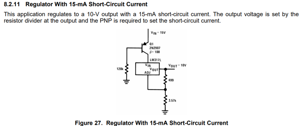
Customer refer LM317L-N SCP circuit and implemented at TPS7B69 trying to limit with 15mA

They tried with R=120kohm and get trip point is about 70mA. Then try and error R=1.2Mohm and get trip point about 7.7mA

Would you please let us know how to calculate for the resistor vs the current limit value? Thanks.

LDO: TPS7B6933QDBVRQ1

PNP BJT:DIODES MMBTA56-7-F

R: 120Kohm --> 70mA; 1.2Mohm --> 7.7mA

Vin: 24V

Vout: 3.3V

Regards,

Allan

  • Hi Allan,

    In the example Vin = 15V.  The collector current would be defined as the current limit in this example.  The voltage across the resistor from base to ground would be Vin - Vbe_on.  Let's say that Vbe_on = -1V.  Then 14V is across the base to ground resistor.  14V / 120k = 117 uA.  The forward gain is called out to be 100 in the example.  So the collector current = 100*117uA = 11.7 mA.

    These older example circuits commonly round values like this to 15 mA.  You will want to test this in your application if you intend on using this technique as the forward gain can change by a lot across temperature.

    Thanks,

    - Stephen