This thread has been locked.

If you have a related question, please click the "Ask a related question" button in the top right corner. The newly created question will be automatically linked to this question.

UCC256304: Fault loop

Part Number: UCC256304
Other Parts Discussed in Thread: UCC256404

Hi,

I'm currently debugging a powersupply based on the UCC256304 LLC Controller. Some PCB's (~10%) enter a fault condition after a while for an unknown reason and we're trying to figure out why, more interesting is that when the fault condition occurs it won't recover from it but keeps retrying indefinitely. Attached below are some measurements performed on the circuit when it entered the fault mode. We can see quite clearly that the bootstrap capacitor starts charging when RVCC becomes available but the top MOSFET's gate never goes high (apart from when RVCC is not ready yet as shown in the figure) and thus the switching never begins. We confirmed that the gate of the bottom MOSFET does go high (as the increasing CBoost voltage shows) and that the SS pin charges but as the top FET doesn't start switching the output voltage doesn't increase. The SS pin voltage doesn't cross the FB voltage this way as the FB pin is still high (since the optocoupler is not conducting).

We already established that overtemperature, BLK voltage and RVCC voltage are OK, do you have any guidance as to how we should debug this further or what state the device is in that is won't enable the top gate?


Yellow: RVCC
Purple: CBoost
Blue: Gate voltage of top MOSFET
Green: SS Cap voltage


Figure 1: RVCC ramping
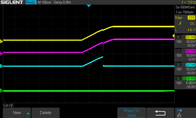


Figure 2: SS ramp


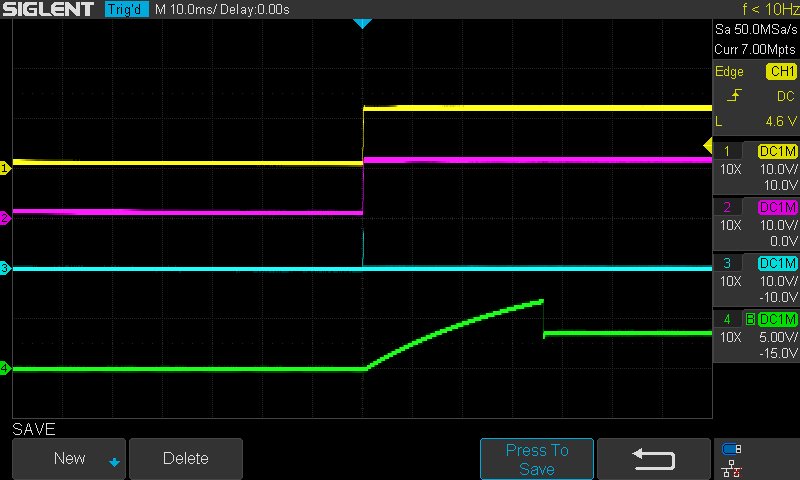
Figure 3: Fault condition loop
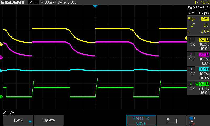


With kind regards,
Willem

  • Hello,

    Your first waveform looks like the boost is being severally loaded by dropping so much.  However, the setting on the scope for that channel is 10V per division is that correct?  If it is you are turning on your LLC too early during inrush and the UCC256304 is going into OCP protection.

    I would suggest  setting the BLK startup threshold voltage to 75% or the regulated boost voltage.

    You can use the excel design calculator to sat the correct OCP and BLK tripoints.  You can find it at the following link.

    If you are still having problems and take further waveforms, could you right the channel number down as well color? 1 in 4 men and 1 in 10 women are colored blind.  Unfortunately I am colored blind.  No worries, I figured out your waveform. 

    Regards,

    Mike

  • Hi Mike,

    Thanks for your reply,The scope division is indeed 10V/div. We will adjust the BLK threshold to delay the turn-on of the LLC. As the fault can take a couple of days to happen we will post an update here it is does. If the fault doesn't happen in the next month or so I will close the case.

    I will place some text in the image the next time to make it clear which signal is which, my apologies.

    With kind regards,
    Willem

  • Hello,

    I have assigned another applications engineer to help you out with this issue.

    Regards,

    Mike

  • HI, 

    What is the bypass capacitance on ISNS pin now? You may need 1000pF on ISNS pin if you have no bypass capacitor here.

    Do you think the issue has been solved? If that is the case, please help to close this thread.

    Yunsheng

  • Hi Yunsheng,

    Currently the bypass capacitor  on the ISNS pin is only 3.3pF, I'll try increasing this although i'm doubtfull it will help as the top MOSFET doesn't switch on (...or very briefly as the IC is powering up) and therefore no current is going through the transformer right now.

    I'll let you know the results when I get them.

    With kind regards,
    Willem

  • Hi, 

    While debugging I noticed that in figure 37 of the datasheet the mentioned fault time of 1 second is indicated by RVCC remaining low for a second, not retrying every second as I am seeing in my measurements. Could you confirm which is correct?

    With kind regards,
    Willem

  • Hi Willem,

    When UCC256304 detects a fault, it will disable RVCC, wait 1s, recharge VCC back up to 26V and then attempt to restart. If you are seeing restart faster than this, a possibility is that VCC is dropping down to 10.5V which would make the controller immediately re-enable its HV startup function.

    Best Regards,

    Ben Lough

  • Hi Ben,

    That's good to hear I started to suspect this as well and can see VCC go down to VCCRestartJfet threshold, this should mean that the UCC256304 is most likely prohibited from switching for some reason and exits STEADY_STATE_RUN with fault code 9 (according to figure 50 of the datasheet). I will look into the waveform generator state machine a bit deeper and report back if I find the reason the converter won't switch.

    Much thanks for confirming the waveform of the RVCC is not what is to be expected in fault mode.

    With kind regards,
    Willem 

  • Hi Willem,

    I would suggest taking a look at UCC256404. This is an upgraded version of UCC256304 with some feature enhancements. UCC256404 is pin to pin compatible with the older UCC256304, just needs some changes to the passive R's and C's around the controller.

    Best Regards,

    Ben Lough

  • Hi Ben,

    A colleague of mine is looking into the UCC256404 parallel to me looking into the occuring error in the circuit (in case this might recur with the new controller).

    Over the weekend the power supply failed again so I could perform some more measurements. Looking at figure 53, the waveform generator state machine I am expecting that either the OVP or OCP error triggers and state transition condition 8 triggers which causes the resets but when measuring the ISNS and BW pins they both remain low. The feedback voltage drops during the restart of VCC but other than that it is higher than the burst mode threshold voltage.I'm kinda lost on what state the controller might be in now, do you have any suggestions as to what can be measured?

    Hope to hear from you.

    With kind regards,
    Willem

  • Hi Willem,

    My thought is that because this is happening at fairly rare intervals, this issue is possibly related to noise coupling into one of the pins that can control switching behavior such as VCR or ISNS at just the right moment to mess things up. The controller is not seeing the expected waveform and is resulting in unexpected behavior and in this case, unable to right itself to recover on its own.

    I do think it is worthwhile to try Yunsheng's idea of increasing the bypass capacitance on the ISNS pin to ~1nF and see if the issue is still present. One of the improvements in UCC256404 is that an Ipolarity change event is digitally filtered internally by the state machine so the UCC256404 is able to reject high frequency noise on ISNS much better than the older UCC256304.

    Best Regards,

    Ben Lough

  • Hi Ben,

    Today we got the first board with the UCC256404 up and running and will test a bunch of these in the coming weeks. 

    As for the UCC256304, the board where the BLK voltage threshold was set according to Mike O's suggestions failed today so I will use that board to patch the 1nF cap on the ISNS line. While we're going with the new controller for our future endeavors I will report back in a couple of weeks if the increased capacitance fixed the error loop in case anyone else gets hung up on the same issue.

    With kind regards,
    Willem

  • The power supply where the ISNS bypass cap was changed to 1nF didn't exhibit any odd behaviour in the last couple of weeks. I suppose the controller got stuck up in an error loop by some transient on the ISNS input pin, anyway, we got the UCC256404 up and running thanks to Benjamin and therefore I'm closing this thread.

    Thanks for all the support and with kind regards,
    Willem