


Hi! I've done the design with two buck converters based on LM5085MY, and both of them can't achieve pre-calculated current limit.
For example one of these converters (the second one is 5.0V 2.1A with exact same layout):
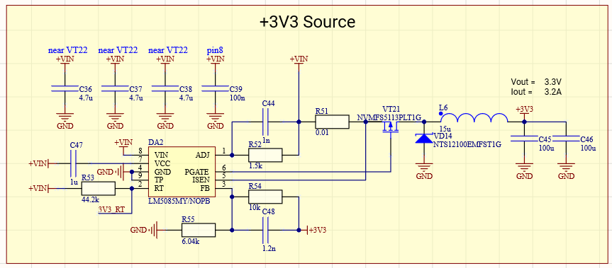

According to the datasheet formula for the current limiter in the schematic with the CS resistor should be Icl = 40uA * R52/R51, with every offset and tolerance included it will be somewhere about (3.9-8.1) A with Iclnom=6 A. But assembled prototype allows drawing only ~(2.8-2.9) A and shuts down after that limit.
It's definitely not a thermal shutdown, the camera shows temperatures about (65-70) C across the converter, plus after lowering the current converter starts to operate immediately. R52 and R51 were double-checked for their values, everything's ok here.
Right now I want to investigate into procurement part before tearing the PCB into pieces to find the reason (there is a possibility that the PCB has the wrong inductor part number, which of course may affect the converter). But it's good to assure that I correctly understood the calculation part and I'm right about my calculations.
Thanks


