This thread has been locked.

If you have a related question, please click the "Ask a related question" button in the top right corner. The newly created question will be automatically linked to this question.

TPS7A19: Input transient protection

Part Number: TPS7A19
Other Parts Discussed in Thread: , MAX3243, MAX232, MAX3232

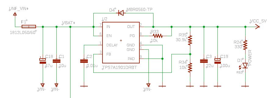
I'm designing this board which essentially consists of RS232 <-> TTL transceivers for a Teensy 3.2 microcontroller. This board is supposed to be installed in a service vehicle, so the expected input voltage is anything up to ~28V, the board is powered from the ignition wire so it turns on only when the engine is run. The output of the TPS7A19 is adjusted to 5V, in fact the circuit and component selection were taken as-is from TI document SBVU031 - TPS7A1901EVM-760 Evaluation Module.

The Teensy receives data from other devices installed in the vehicle (sensors like RoadWatch, AVL etc.) through its 3 serial ports, the TTL to RS232 conversion is accomplished with a MAX3243:

The problem I'm facing is that I've had a handful of boards where the TPS7A19 was killed if power was removed from the board while any device is connected to one of the serial ports (via RS232_TXn, RS232_RXn and GND). When the TPS is dead the POWER led won't come up and OUT remains at zero, although the FB voltage is still at 1.233V. Replacing the TPS fixes the problem.

I couldn't find a specific reason for this behavior. If there are no other devices connected to the board's serial ports (thus no other external ground connections), none of this happens and the TPS survives. I can only assume this is some kind of capacitor discharge transient causing a load dump and this is getting back to the input of the TPS through the reverse current protection diode D4. Yet, I couldn't catch on the scope the supposed surge that would be killing the TPS.

I've been told by some to suppress D4 and install a TVS at the voltage input; other posts here on E2E suggest adding a schottky diode from GND to IN to prevent negative voltages exceeding the Absolute Maximum Ratings from reaching IN/EN.

Any suggestions on how to prevent the TPS from being fried are welcome.

Regards,

Claudio

  • Hi Claudio,

    Something I noticed about the TPS7A19 schematic is that pin 4 is connected to analog GND, but pin 5 is connected to some other voltage. Is that a separate reference voltage or something like that? What is the reason for having the 2 GND pins connected to different nets?

    Is the 5V output from TPS7A19 powering the devices connected to the serial ports as well or is it only powering the MAX3243? The total current is estimated at about 300uA in the datasheet and I don't see a whole lot of capacitance, so if only the MAX3243 is powered by TPS7A19 it seems unlikely to me that ABS MAX is being violated at the output. 

    By TVS do you mean a diode? I.e. a protection diode at the input?

    Best regards,

    Nick

  • Hi Nick,

    Both pins 4, 5 and the thermal pad are actually connected to the same ground, they're just separate ground planes for the input voltage (VIN-) and the digital ground used troughout the board, they're connected on a single point at the TPS7A19's ground pins.

    The 5V from the TPS7A19 is powering only the Teensy and the MAX3243, not the external devices. With all the LEDs and whatnot the current consumption at the output of the TPS7A19 is currently around 110mA, I don't think overload is actually a factor here.

    By TVS indeed I mean a protection diode at the input, perhaps a transient suppression diode such as the P6KE or alikes. But I'm not entirely sure my problem is on the input stage, anyway.

    Regards,

    Claudio

  • I've done some extra testing and I found something quite amusing (and perhaps the reason the TPS7A19 is failing): If I leave the board completely disconnected from any power source, but at the same time I leave any device connected to one of the board's serial ports (Tx, Rx and Gnd are the only pins in use), the MAX3243's charge pumps seem to be "leaking" negative voltage to the VCC_5V net and this would be exceeding by far the absolute maximum for the OUT pin:

    In this scopeshot the yellow waveform is the RX pin on the RS232 side, and the blue waveform shows the VCC_5V net, which is receiving voltage as low as -7.6V.

    I've used MAX232/3232's on other projects in the past and I don't remember seeing any behavior similar to this. Or I might be getting slightly senile, who knows :p

    Regards,

    Claudio

  • Hi Claudio,

    That is quite interesting!

    So you say the board is completely disconnected from any power source. I'm a bit confused by this; was the board powered before and then disconnected? I'm not understanding how the charge pump could be working without any power source. 

    Regards,

    Nick

  • Hello Nick, I think I had a bad MAX3232, I replaced it and never had any negative voltage flowing into the 5V line again. But to answer your question:

    So you say the board is completely disconnected from any power source. I'm a bit confused by this; was the board powered before and then disconnected? I'm not understanding how the charge pump could be working without any power source.

    Indeed, the board is completely disconnected from any power source. The only connection the board had to an external device is to a spreader controller (http://www.dickey-john.com/product/control-point-control-system

  • Anyhow, that still leaves me with the dying TPS7A19 problem. I traced back the event that causes the TPS7A19 to die to the following: When my board is completely disconnected from the power source AND I have the spreader controller up and working, the TPS7A19 dies as soon as I connect the RS232 cable to my board. I went ahead and removed the TX/RX pins from the connector (thus leaving only the GND pin), and as soon as my board is connected to the spreader controller ground, it dies. 

    I don't know what's inside the spreader controller, if it has an isolated power supply or whatever, the fact is the TPS7A19 dies as soon as the GND wire from the spreader controller is connected. On the other hand, if i first connect my board to vehicle power and only then I connect the spreader controller, nothing happens -- I can connect and disconnect it as much as I'd like and the TPS7A19 survives. 

    Another amusing fact is that if I jerry-rig any 7805 in place of the TPS7A19, it works under any circumstance...

    Again, it seems the TPS7A19 is dying from the output side; Even after it dies the 1.233V at FB pin is still there if I power it from external power. 

  • I should add that this problem has occurred to some 15 boards already, so it's safe to assume it's not a one-off failure.

  • Hi Claudio,

    Do you have a schematic you can share to help me understand the connections? It is difficult for me to diagnose the problem otherwise because I am not familiar with the other devices in your system. Can you also get some scope shots of the Vin, Vout, Iout for the TPS7A19 when you connect the ground of the spreader controller and the TPS7A19 dies so we can see exactly what is going on?

    Best regards,

    Nick