This thread has been locked.

If you have a related question, please click the "Ask a related question" button in the top right corner. The newly created question will be automatically linked to this question.

TLV803: Unexpectedly high rising threshold for 4.38V nominal part

Part Number: TLV803

I am seeing in several TLV803MDBZR parts from the same batch that the rising threshold is at about 5.04V.  Falling threshold is about 4.27V, which is within tolerance by the datasheet.  Unfortunately 5.04V is too high for our system power supply.  According to the datasheet, the hysteresis for this part should be 60 mV typical, although I don't see a max spec  Another thread said that the maximum rising threshold should be more like 4.54V.  In any case I would not expect VIT+ to be so high.  Are these parts defective, or is this an expected behavior for the TLV803M?

  • Hi Gabor,

    Is it possible for you to share a schematic with me?  Are these measurements from the EVM board?  The values don't make sense to me.  The falling threshold should be around 4.38V.  If you are measuring 4.27V, that is outside the spec min range.  

    Ben

  • Hi Ben,

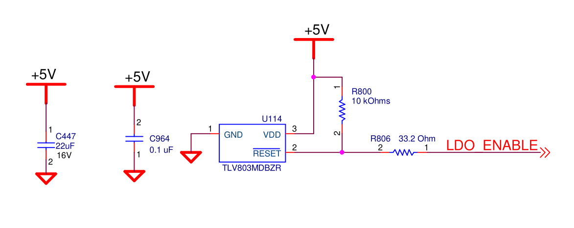
      It's not the EVM board.  Here's the relevant bit from the schematics:

    Right now I'm using a lab supply for +5V.  It has an output voltage resolution of 10mV.  The output goes high when I step from 5.03 to 5.04 and low when I step from 4.28 to 4.27.  The thresholds are very repeatable.  The datasheet shows a range of 4.28 ~ 4.48 for the low-going threshold but I don't see a value for high-going threshold.  In any case it's the high-going threshold being above 5V that causes a problem in the system, since the actual power supply for the product is 5.0V nominal and often comes in 1% low.  My understanding was that the high-going threshold should still be significantly less than 5V.  I measured voltages right at the pins of the TLV803 and saw the same voltage shown on the lab supply, so I don't think anything else in the circuit would be keeping the reset signal active.  LDO_ENABLE goes to three LDO regulators whose input is the same +5V.

  • Hi Gabor,

    The going-high threshold is (VIT-) + (VHYS) = 4.38V + 60mV = 4.48V (using typ values).  Are all the LDO_ENABLE inputs high-impedance?  If you can do me a favor, can you remove R806 and repeat your measurements?  I want to ensure that there is nothing downstream affecting the measurement.  From the looks of the schematic, everything seems correct.

    Ben

  • Hi Gabor,

    Is it possible that you can capture some scope photos and verify the DC node voltages?  Thanks,

    Ben 

  • Hi Gabor,

    If you don't mind, can you close this thread?  I am working with the FAE who is on this project.  Thanks!

    Ben 

  • Thanks, Ben.

      In the end it turns out the part is in fact working within the expected range of VTH+ and VTH-.  The issue was a dip in the input voltage when the additional LDO regulators turned on due to the inrush current.  This dip created a new reset pulse quickly enough that the dip didn't affect DC measurements.  On the scope it was evident that the LDO_ENABLE output was going high briefly every 200ms or so.  Only when the supply started at above 5V was this dip above the low-going threshold allowing LDO_ENABLE to go high and stay high.

  • Hi Gabor,

    I am glad to hear that you have found your issue.  Good luck with your project!

    Ben