This thread has been locked.

If you have a related question, please click the "Ask a related question" button in the top right corner. The newly created question will be automatically linked to this question.

TPS7A33: TPS7A33 test condition of Figure 14 in datasheet

Part Number: TPS7A33

Hello team,

My customer woudl like to select the output capacitor(47uF)  and they think that they should consider ESR for Cout selection because "High-ESR capacitors may degrade PSRR and affect stability." is written in the datasheet (Page 16)

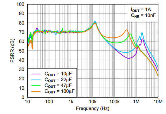
They have some questions about the relation of Power-Supply Rejection Ratio vs ESR of COUT, and test condition about PSRR (Figure 14. Power-Supply Rejection Ratio vs COUT). Would you please advise?

1) Are there any data of Power-Supply Rejection Ratio vs ESR of COUT?

2) What is type number (or ESR) of Cout (10uF, 22uF, 47uF and 100uF) for PSRR test  of Figure 14. Power-Supply Rejection Ratio vs COUT?

3) Would you share the schematics for PSRR test ?  What is Vin voltage?  What is Vout voltage?

Your advice would be so appreciated.

Best Regards,
Akihisa Tamazaki

  • Hi Akihisa,

    We do not have any direct data for PSRR vs ESR of COUT. However, we can analyze the effects of ESR other ways. Using Murata's SimSurfing online tool, I've pulled up the impedance characteristics for a couple capacitors with capacitances 10uF and 100uF because we know that ESR is typically lower for larger capacitors. The following shows the impedance for both caps:

    Notice that the lowest impedance point is at a lower frequency for the 100uF cap, which has a lower ESR. What is important here is that the lowest point (or the region that is close to the lowest point) is further within the bandwidth of the LDO itself, which is typically around a couple hundred kHz. What this means is that we get better filtering from the cap for the frequencies that are in play.

    Akihisa Tamazaki said:
    2) What is type number (or ESR) of Cout (10uF, 22uF, 47uF and 100uF) for PSRR test  of Figure 14. Power-Supply Rejection Ratio vs COUT?

    ESR is not something that is recorded during these tests. However, we can take a look at Figure 14 and along with the explanation above we can draw some conclusions.

    The first peak is the same for all output cap sizes because it is a result of the pole locations of the LDO itself. The second spike is a result of the output capacitor. Notice that for the orange line (for COUT = 100uF), the second spike happens at a lower frequency than the others. This is again beneficial for the PSRR because within the LDO's bandwidth the PSRR has been increased. 

    Akihisa Tamazaki said:
    3) Would you share the schematics for PSRR test ?  What is Vin voltage?  What is Vout voltage?

    For PSRR measurements, we use a Bode 100. The input cap is removed so that the input can be driven easily with an AC signal. The input and output are as described at the top of the plots:

    The absolute values of the input and output voltage will have an effect on the PSRR, but more important is the headroom available. The input has a superimposed AC signal with a magnitude such that at the low point the LDO does not enter dropout. For this test, Iout = 1A as in Figure 14. 

    Best regards,

    Nick

  • Hello Nick-san,

    Thank you so much for your reply and detailed analysis for ESR vs. PSRR.
    I understood it. When the customer has additional questions, I may ask you again.

    Best Regards,
    Akihisa Tamazaki

  • Nick-san,

    The customer has additional questions. Would you please advise?

    1) You showed the impedance characteristics  10uF and 100uF ESR vs frequency  Using Murata's SimSurfing online tool. What  did you select type number of 10uF and 100uF capacitance?

    2) What is type number of Cout (10uF, 22uF, 47uF and 100uF) for PSRR test  of Figure 14 in the datasheet?

    Your help would be so appreciated.

    Best Regards,
    Akihisa Tamazaki

  • Hi Akihisa,

    Akihisa Tamazaki said:
    1) You showed the impedance characteristics  10uF and 100uF ESR vs frequency  Using Murata's SimSurfing online tool. What  did you select type number of 10uF and 100uF capacitance?

    I chose the capacitors at random to show that the ESR for larger capacitors is generally lower. To answer the question, the plots are directly showing ESR vs. frequency. You could define the single value for ESR as the resistance at the lowest point, so the ESR for the 10uF cap is about 3mohm @ ~1MHz and for 100uF is about 1mohm @ ~200kHz. You may want to explain that the ESR is often defined as a single number but is not actually a constant number, as seen in the plots. 

    Akihisa Tamazaki said:
    2) What is type number of Cout (10uF, 22uF, 47uF and 100uF) for PSRR test  of Figure 14 in the datasheet?

    We do not have the ESR values for the capacitors used to generate Figure 14. However, we do know that the capacitors were ceramic so you can assume that the ESR is less for higher capacitance values and the plots I've provided are likely a good reference point for the caps used in Figure 14. I.e., the 10uF cap likely has ESR roughly around 3-6mohm @ about 500kHz-1MHz and the 100uF cap is likely roughly around .5-1.5mohm @about 100-200kHz, and the in between values lie somewhere between these. 

    Best regards,

    Nick

  • Nick-san,

    I'm sorry for the misleading question.

    About Question 2)
    The customer would like to know type number of Capacitor in Figure 14 in the datasheet. e.g. GRM188D70E476ME01# made by Murata which is 47uF.  They do not want to know ESR value.

    Would you please look into type number of Capacitor?

    Your help would be so appreciated.

    Best Regards,
    Akihisa Tamazaki

  • Hi Akihisa,

    Sorry for the confusion. 

    I've talked to the engineer that did the characterization and the exact part numbers were not recorded during testing. They said they use X5R or X7R caps and likely 0805 for the ease of soldering. That is about as specific as we can get since we don't normally record the exact part numbers.

    Best regards,

    Nick

  • Nick-san,

    I understand.
    Thank you so much for your kind support.

    Best Regards,
    Akihisa Tamazaki