This thread has been locked.

If you have a related question, please click the "Ask a related question" button in the top right corner. The newly created question will be automatically linked to this question.

LM3429: LM3429

Part Number: LM3429
Other Parts Discussed in Thread: TPS92692, TPS92691

Hi All,

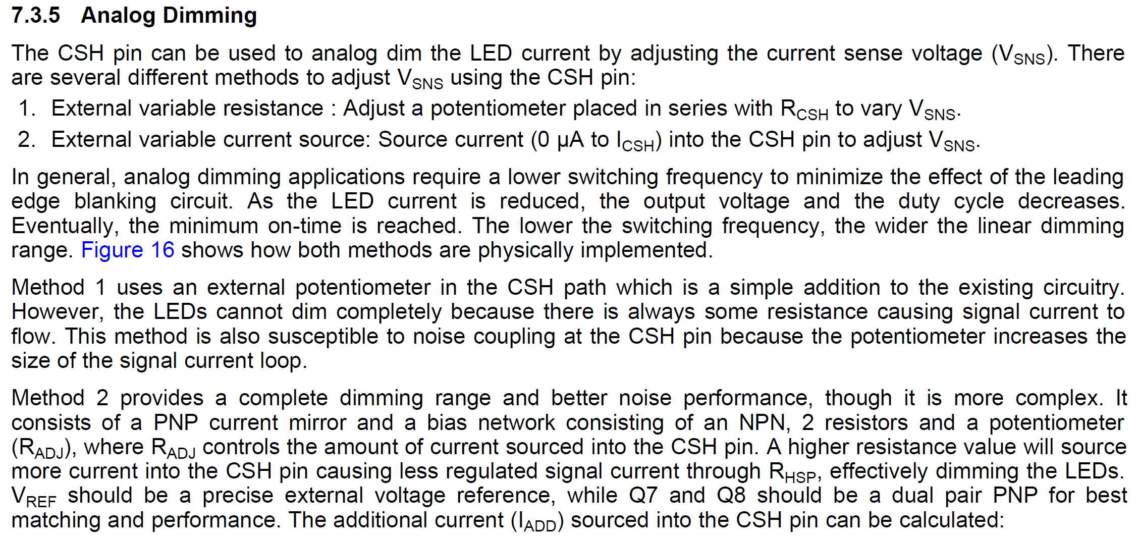
It is a very simple question. I am doing an application using the LM3429 and I need to use the analog dimming functionality. I would like to use the method 1 to dim the light to 10% power. The datasheet specifies this:

"Method 1 uses an external potentiometer in the CSH path which is a simple addition to the existing circuitry.
However, the LEDs cannot dim completely because there is always some resistance causing signal current to
flow. This method is also susceptible to noise coupling at the CSH pin because the potentiometer increases the
size of the signal current loop"

My 100% is 0.6A and my 10% will be 0.06A. Can I reach this low with analog dimming?

If to achieve 100% my CSH resistor is 12.4k with ICH  being 100uA, I think to achieve a 10% I need to put a CSH resistor of 124k, is this correct?

Kind Regards

  • Hi Daniel,

    Without knowing all your applications and in general as stated in the data sheet the resistor method has a susceptibility to noise with higher resistance and can have issue with high dimming ratio.  The second method of adjusting current requires variable current source and that's a lot of external parts.  I would recommend the TPS92691 or TPS92692 for what you are trying to do where analog current adjust is easier done and will meet you requirement. 

    Thanks Tuan

  • Hi Tuan,

    What extra information do you need?. If it didn't pick any noise, could you say that it would be a 10% of the full power?,

    Thaks.

  • Hi Daniel,

    If it didn't pick up noise or the minimum duty cycle getting close to the leading edge blanking time then yes it will work.  However, because of the high dimming ratio there can be issue with it in your application.  The higher resistance and lower current as stated in the data sheet for method 1 which you are trying to do and there is also the minimum ON time that can get close to the leading edge blanking.  Please see section 7.3.5 for this explanation.  This is why I recommend the TPS92691 or TPS92692 which are newer parts with fixed frequency control and will achieve this easier.

    Thanks Tuan

  • Possible mitigations to resolve this issue without having to use another driver?

  • Hi Daniel,

    I understand.  You will need to prototype your design here and choose a frequency of operation that you will not get to the limiting factor of leading edge blanking.  If you stay away from that and if there is no noise factor then it can work.

    Thanks Tuan

  • Hi,

    Understood, thanks.

    I have a question about thermal management:

    The Junction to ambient  thermal resistance and junction to board thermal resistance are not related with a defined footprint. How do I estimate the wattage dissipated by the driver?. Do I use a typical efficiency of 90%  using junction to ambient thermal resistance?

    If I don't use the analog input  but instead I just change the Rsense with a switch , would I lead the edge blanking?

  • Hi Daniel,

    You cannot use the 90% efficiency and all that power dissipation is in the LM3429 driver.  The power loss is mostly in the power stage components like the inductor, FET and output diode.  The power dissipated in the LM3429 is dependent on input voltage and the external FET used.  Usually it's best here to get a evaluation board or do a prototype of your design to figure that out.   The layout also effect the junction temperature of the part.

    Thanks Tuan