This thread has been locked.

If you have a related question, please click the "Ask a related question" button in the top right corner. The newly created question will be automatically linked to this question.

TPS7A85A: Using diodes on ANY-OUT pins

Part Number: TPS7A85A
Other Parts Discussed in Thread: CSD13201W10

Hi Stephen,

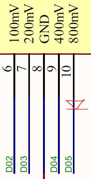
I am using an NI I2C/SPI/DIO box to send digital in/out (DIO) signals to ANY-OUT pins of TPS7A85A IC. The NI box has a weak pull-down (40kohms) resister on their DIO lines which is not letting me create an OPEN to the ANY-OUT pins. When I put the DIO lines from NI-box in tri-state/open state, it presents itself as a short to the ANY-OUT pins of the LDO. As a solution, I am thinking about putting a Schottky diode on the ANY-OUT pins in a manner as shown below? Have other customers of yours used this strategy? Do you think it will work? If it will work, can you please suggest a part number for the diode that is hopefully not too big? Do you have alternate solutions to solve this problem?

Thanks,

Noman 

  • Hi Noman,

    I have not come across any customers who have used this technique before, but I believe there would be some variation in the results as the nonlinear resistance of diodes is a function of the current.  As each resistor inside the IC has a different value, there would be slightly different currents flowing through each schottky diode and that would result in a slightly different ON resistance.  This will also change the divider ratio slightly, changing Vout slightly from what the datasheet would suggest.

    I would suggest using a small signal MOSFET to enable / disable each ANY-OUT connection.  As long as the voltage from your TE is sufficient, you can turn on an N-channel MOSFET to pull the ANY-OUT connection to ground.  Would that work for you?  I've used this technique in the past on switch mode power supplies to achieve a similar concept and I believe it would work well for this application. 

    Thanks,

    - Stephen

  • Hi Stephen,

    The ON resistance of the diode should be negligible compared to the resistors inside the IC. Do you really think it can effect the divider ratio and hence Vout? My RFIC has a very strict requirement of Vdd. To the extent possible, I don't want to have any impact on VOUT because of the diodes. Do you have any idea how much current (or range of current values) can flow through the shunt resistors connected to ANY-OUT pins of the IC? If I know the max current that will go through the diode, I can find a diode that has a small ON-resistance that doesn't effect Vout. I am setting Vout to 1.8V and my maximum load current will be 4A.

    Regarding the FET/BJT idea, I don't mind using it. Can you suggest a part number that you have used in the past and think will work well in my application? 

    Thanks,

    Noman

  • Hi Noman,

    At these voltages and currents, there are almost an unlimited number of discrete MOSFET's to choose from.  A 2N7002 or equivalent will probably work just fine.  You just need to decide how small you need to go to (plenty of options even smaller than a SOT-23).

    The current flowing out of the ANY OUT pins depends on the output voltage they are connected to.  But here are the values for your reference:

    Thanks,

    - Stephen

  • Hi Stephen,

    So are the voltages on the ANY-OUT pins across the resistor (e.g. 6.05kohm) connected to that pin?

    Also on page 21 of the datasheet it says "R1 and R2 can be calculated for any output voltage range using . This resistive network must provide a current equal to or greater than 5 μA for dc accuracy. TI recommends using an R1 approximately 12 kΩ to optimize the noise and PSRR." Is this 5uA current flowing through R2 to ground or into the FB pin?

    Finally is your reservation on diodes mainly because of variability of RDS(ON) with respect to diode current or are there other factors as well? It's just that diodes are smaller two pin devices whereas transistors are bigger. But obviously I am looking for the better solution here. So I am fine with either.

    Thanks for your support and fast responses. I really appreciate it.

    Regards,

    Noman

  • The voltage from FB pin to ground will be the reference voltage, which for this device is 0.8V.  So 0.8V is across the low side set of ANY-OUT resistors, but only the ones that you physically connect to GND will see the 0.8V. 

    The feedback pin current may be flowing into or out of the feedback pin.  The electrical table shows that it is +/- 100 nA maximum.  The guidance on 5 uA comes from a common rule of thumb to swamp out this nonideal feedback pin current by 50x - 100x.  In this case they chose 50x.  The 5 uA would be flowing through the feedback resistors from Vout to GND but it is only applicable if you are choosing your own feedback resistors using external resistors.  If you are using the internal ANY-OUT resistors then you don't have to worry about this 5 uA guidance. 

    My observation on the diodes is mainly the variability of the on resistance.  Lets say you tied 6.05k to GND through a schottky diode.  The current flowing through it will be small: a first order calculation is 0.8V / 6.05k = 132 uA.  The IV curve for some very small diodes places that around 100 mV drop.  So the dynamic impedance is something like 756 ohms.  It will cause a slight shift in the setpoint.  This is much different than a MOSFET where the Rds(on) is orders of magnitude lower.  For small signal MOSFET's you can find very small component sizes, such as the CSD13201W10 N-channel MOSFET:

    https://www.ti.com/lit/ds/symlink/csd13201w10.pdf?HQS=TI-null-null-digikeymode-df-pf-null-wwe&ts=1605220967197

    Thanks,

    Stephen