This thread has been locked.

If you have a related question, please click the "Ask a related question" button in the top right corner. The newly created question will be automatically linked to this question.

TPS40425: 2-phase total power and GUI monitor issue

Part Number: TPS40425
Other Parts Discussed in Thread: CSD95372AQ5M, , TPS40428

Hi Sir,

may we learn from you this issue,thanks.

I use TPS40425+CSD95372AQ5M for application design

Read current and power consumption through GUI, such as 1.8V(operating Two-phase).

The total current is CH#1 plus CH#2, right?

Total power consumption: 1.8*(10.5+9.1) =35.28W

But the GUI shows that CH#1 is 1.814v*10.563A = 19.16W and CH#2 is 1.814v*9.125A≠19.16W (total 19.16+19.16=38.32W).

The results are not consistent. How do we look at this?

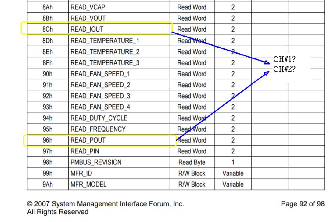
How to readout if I use I2C?  According to PMBus, is 0x96 Pout? 

CH#1 or CH#2 or CH#1 +CH#2 ?

  • The device does not support PMBus READ_POUT. The GUI is calculating Pout as READ_IOUT * READ_VOUT for display purposes.  

    The GUI seems to be getting confused by the fact that this is a 2 phase design. In this case, Pout should be Vout*(I1 + I2). 

    In other PMBus controllers, the GUI can poll READ_IOUT with PAGE=0xFF to get the summed current. But this controller does not support it. 

    So, in summary, current is reported phase-wise in Fusion and this makes the Pout calculation incorrect. 

  • Yes, it's 2 phase design.

    As described in reply,If I need to know the correct power consumption, I should read out Vout and Iout1/2 for calculation.

    In this case, TPS40425+CSD95372AQ5M is Non Smart-Power Operation but the current value is not accurate.

    Can you help to check schematic if i change CSD95372A to CSD95378B.

    Schematic as attachment.

    Regards,

    NelsonTPS40425-CSD95378B_3.3V-30A.pdf

  • Hello, 

    Have you calibrated the current sensing with the IOUT_CAL_GAIN and IOUT_CAL_OFFSET commands? The default setting for this device is appx 0.5mOhms. But your schematic indicates a nominal DCR of ~0.29mOhms. This will cause a gain error in the current readings. 

  • Yes, the DCR of this part is 0.29mOhm and I have filled in this value. As show below,

    Under light load (about 0.1A), Iout is displayed at 2-3A.

    So I want to change to CSD95378B for current sensing.

    Regards,

    Nelson

  • I see. 2-3A at 0.29 mOhms is only around 900uV. This is normal for the TPS40425 current sense amplifier offset. 

    Switching to CSD95378B may or may not eliminate this offset, as the smart power stage has its own current sensing accuracy specs. Also, you may want to use TPS40428, as it is defaulted to Smart power stage mode at power-on. 

    Your best option may be to calibrate this offset with IOUT_CAL_OFFSET.