This thread has been locked.

If you have a related question, please click the "Ask a related question" button in the top right corner. The newly created question will be automatically linked to this question.

UCC256301: Fail ! unable to work properly

Part Number: UCC256301
Other Parts Discussed in Thread: PMP20795, UCC25630-1EVM-291, UCC256304

Hi team

I started to study LLC in the last six months. The chip used is Ti’s UCC256301. Our design goal is:

Input voltage: 340V~410V Output voltage: 100V

Output current: 4A

Efficiency: 93%

According to this parameter, I made the following choices for the LLC parameters

Lm = 300uH  Lr = 55uH Cr = 44nf Q = 0.46 K=5.4

I use PMP20795 as a reference design

I have to say, the design is almost the same.

Except for different transformers and inductors, and some component parameters, the layout is exactly the same

The parameters around the chip are also configured according to excel

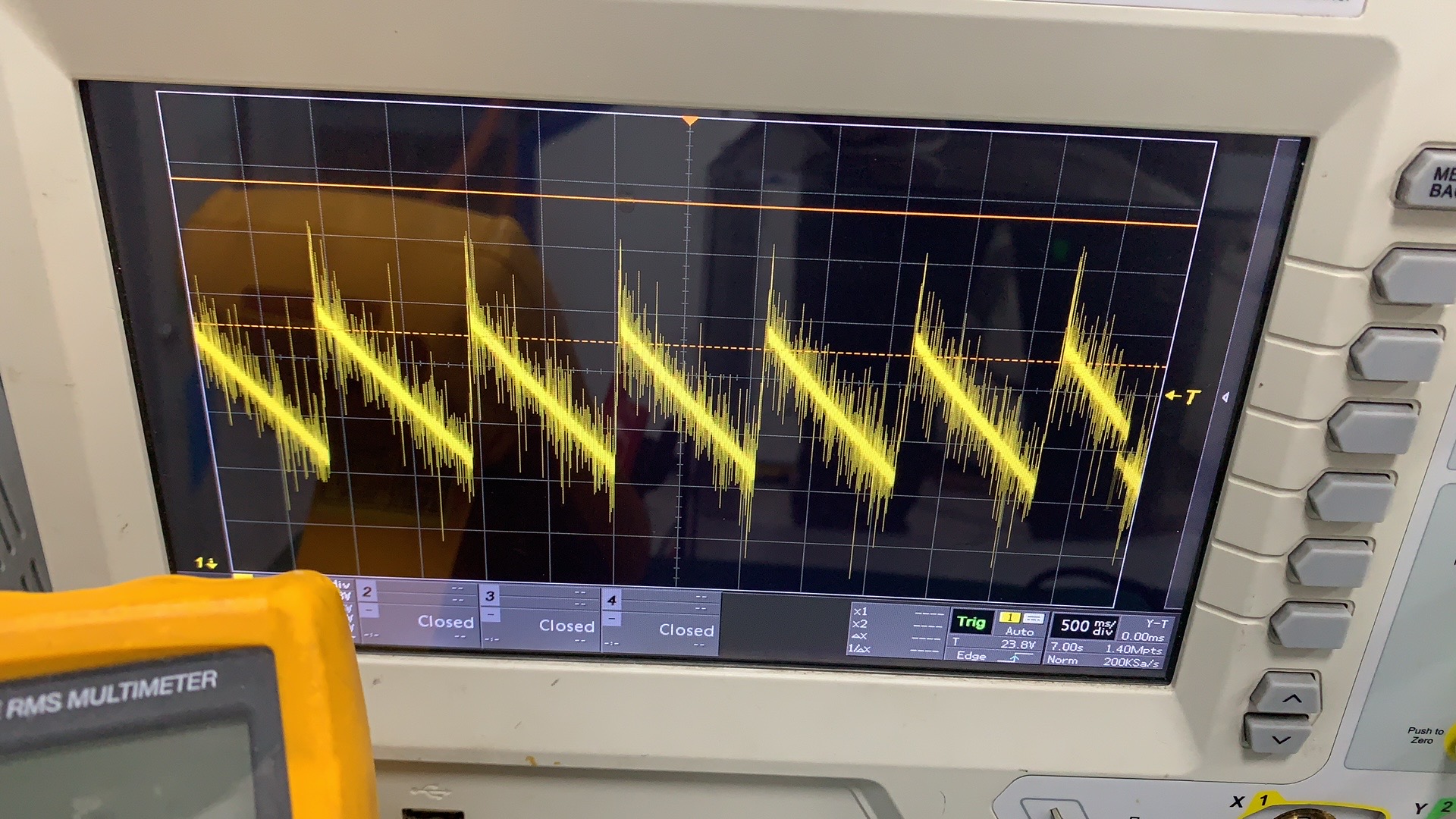
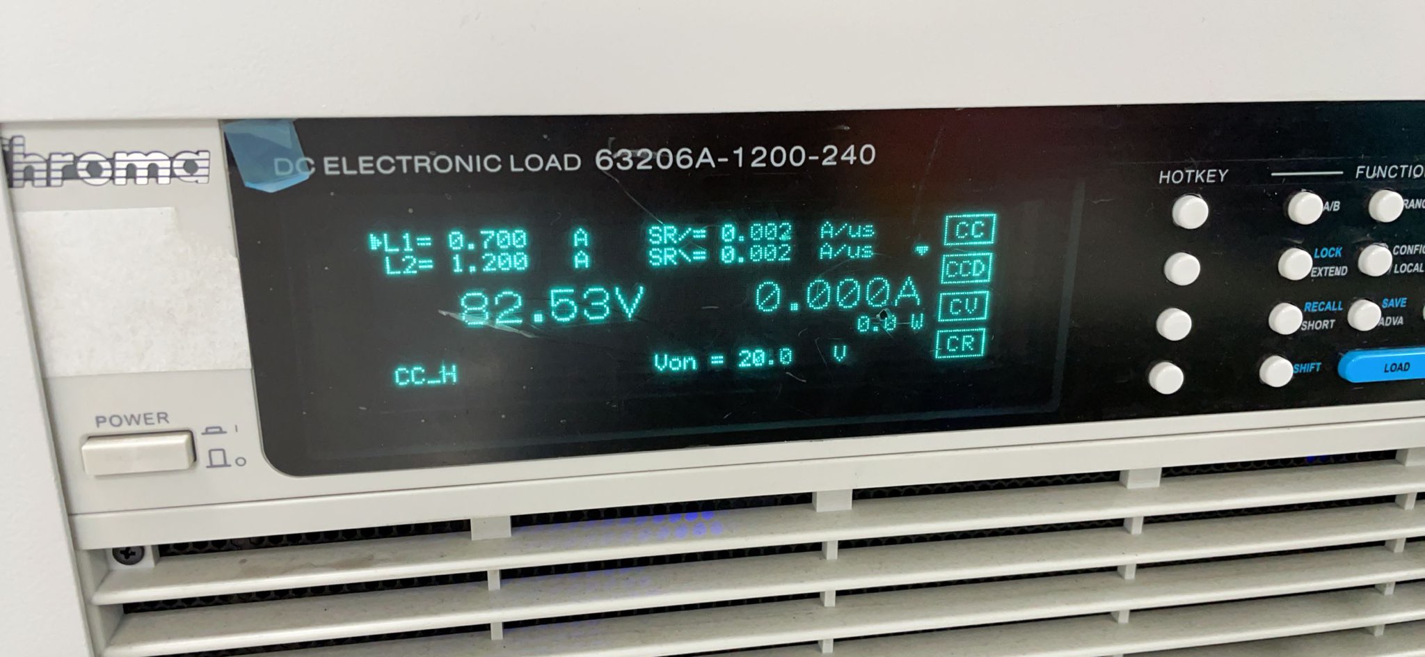
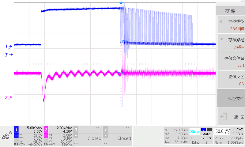
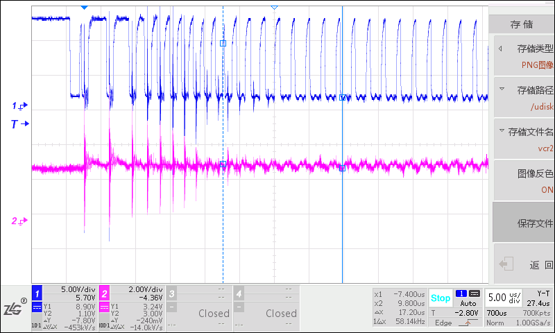
But still unable to output voltage normally

I don’t know where the design went wrong, I have provided the schematic and layout files, hoping to help me solve the problem

LLC400W_SCH_REV01_Oct-21-2020.pdf

JP-2W15482912020116193.zip

Thanks a lot

Best Regards

Eilision

  • Hi Eilision,

    Sorry to hear about the trouble. What I would suggest is to take a look at the LO pin to determine if the LLC is attempting to switch every 1s. If yes, the device is detect a fault (likely OCP or OVP). My initial thought is that the bottom VCR capacitor is quite big and this is causing the initial switching frequency during startup to be a bit low which is resulting in OCP being detected.

    If you are able to share waveforms of VCR, ISNS, BW and LO when the LLC attempts to switch, it would help determine the issue.

    I also want to mention we have an upgraded version of UCC25630x called UCC25640x. It may be worthwhile to use this device instead.

    Best Regards,

    Ben Lough

  • Hi Ben

    I checked the waveform of the RVCC pin and it restarted every second, presumably because the fault restarted.

    I shorted the resistance of the ISNS pin to GND to rule out the cause of OCP.

    I designed the capacitor of the VCR to be a bottom capacitor of 20nf. After the problem occurred, I immediately changed the value of the capacitor and reduced it to 6.8nf, but it still couldn’t solve the problem....

    I only saved the voltage waveform of the VCC pin, and the rest needs to be retested to provide.

    I bought your demo board UCC25630-1EVM-291, it can work normally, I can’t understand why I can’t output the voltage

    Thanks a lot

    Best Regards

    Eilision Xie

  • Hi,

    can you show any waveform to show the unstable issue?

    I would suggest you probe vout, Lo of primary LLC low side driver, SS pin voltage and resonant current together when you found the unstable phenomenon.

    thanks.

  • Hi Ben,

    Sorry, due to improper operation during the test, the previous sample was damaged, I re-soldered a piece, I will give you the test waveform you need below, blue is the waveform of LO, red is the waveform of VCR, ISNS, BW respectively .

    The first is the test waveform without load.

    The picture below is the waveform of LO pin and VCR pin without load

    The picture below is the waveform of LO pin and INSNS pin without load

    The picture below is the waveform of LO pin and BW pin without load

    Then the test waveform under the condition of 0.7A load

    The picture below is the waveform of LO pin and VCR pin under load

    The picture below is the waveform of LO pin and ISNS pin under load

    The picture below is the waveform of LO pin and BW pin under load

    Thanks a lot

    Best Regards

    Eilision Xie


  • Hi Eilision,

    The amplitude of the gate pulses are slowly drooping as switching continues during the startup. It looks like VCC might be drooping too much and is causing the controller to shut off due to not enough VCC voltage. Could you try removing D6, use a bench supply to apply 15V across C22 and try to start up the LLC? This chould help confirm if this is the issue or not.

    Best Regards,

    Ben Lough

  • Hi Ben,

    Your suspicion is that the output energy of the auxiliary winding is not enough?

    I have done this kind of test before. I once connected a large electrolytic capacitor in parallel with the electrolytic capacitor of C28, so that when the high voltage starts, the large electrolytic capacitor will be charged enough to replace the constant current. Power source to supply power to VCC to confirm whether it is the auxiliary winding problem.

    Of course, my experiment was unsuccessful. My friend thought my method was wrong, so I followed your suggestion, and the situation is still the same

    .So I don’t think it’s the auxiliary winding problem for the time being

    By the way, do you have special requirements for winding transformers?

    Thanks a lot

    Best Regards

    Eilision Xie

  • Hi Eilision,

    You cannot apply voltage directly to VCC as this would interfere with the HV startup function wanting to charge up VCC to 26V before switching begins and would fail to start up. But if you apply the external voltage to the anode of D11, it should be fine. Do you still see the droop in the LO amplitude when using the external DC supply at C22?

    There is no special requirement for the aux winding. VCC voltage just needs to be kept in the recommended range

    Best Regards,

    Ben Lough

  • Hi Ben,

    I applied voltage directly to the anode of D11 and the phenomenon still exists.

    But I’m glad you raised a question that I overlooked. I haven’t paid attention to the level drop of Lo. I now suspect that it may be the problem of my mos tube, because the reverse recovery time of the mos I used is 530ns and that of PMP20795 The reverse recovery time of mos in bom is 150ns.

    I have repurchased the mos recommended in bom, I will try again.

    Thanks a lot

    Best Regards

    Eilision Xie

  • Hi Ben,

    I am glad that I have output the voltage and current normally, I replaced the ucc256304 chip and MOS tube, thank you for your help

    Thanks a lot

    Best Regards

    Eilision Xie