This thread has been locked.

If you have a related question, please click the "Ask a related question" button in the top right corner. The newly created question will be automatically linked to this question.

LM3481-Q1: Leakage Current at FA pin

Part Number: LM3481-Q1

Hi Team,

My customer is working on following design to set LM3481-Q1 frequency, the zener diode here is to clamp FA pin voltage to be lower than 6V, please refer to another E2E thread for more detail: https://e2e.ti.com/support/power-management/f/196/t/934878?tisearch=e2e-sitesearch&keymatch=LM3481-Q1 

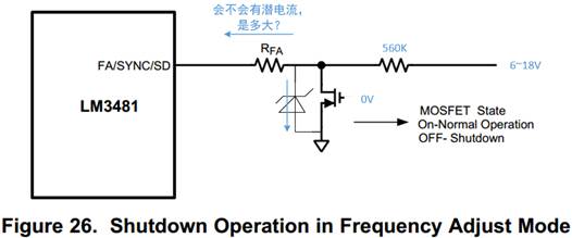
Because some of the OEMs will have requirement on KL30 leakage current, so customer want to know, besides the leakage current of the zener diode, if there'll be any leakage current drawn into FA pin of LM3481-Q1? Or we can take it simply as high impedance?

Thanks.

Best Regards,

Livia

  • Hello Yazhu,

    The expert for this device will be back in the office next week.

    In general the leakage of an input pin should be negligible compared to the leakage of the Zener diode.

  • Hi Yazhu,

    Sorry for the delay owing to the holidays.  The FA pin is usually regulated at about 1V during operation (RFA grounded).  If the external FET is off, the FA pin can be raised by external source to exceed the 1.3V threshold to shut down the the IC.  In this case, the FA pin can be considered high impedance.  

    Thanks,

    Youhao

  • Hi Youhao,

    Thank you for the reply.

    For the UVLO function, It's written in the datasheet that "If the UVLO pin function is not desired, select R8 and R7 of equal magnitude greater than 100 kΩ". May I ask why with larger than 100k R8/R7 could disable UVLO? Is it because UVLO pin need some bias current to function?

    Best Regards,

    Livia

  • Hi Livia,

    What it said was not to disable the UVLO, but to prevent it from stopping the operation once VIN is above the recommended min operating voltage, which is 2.97V.  the equal R7 and R8 will automatically set UVLO pin voltage above the 1.43V thresh hold.  

    Hope this clarifies,

    Thanks,

    Youhao

  • Hi Youhao,

    You also mentioned that during operation, FA will be regulated to around 1V. If customer configure FA pin as picture above, when the external FET is on, the resistor RFA is actually connected to GND through a small VDS, let's say 0.4V, will this 0.4V affect the accuracy and the calculation(RFA=(22*10^3)/Fs-5.74) of the frequency?

    Thanks.

    Best Regards,

    Livia

  • Hi Livia,

    It will but your assumption is not realistic unless you use a very large Rdson FET.  Usually Rdson and RFA forms a resistor divider and you will have  negligible Vds considering RFA is in the range of kOhms.

    Thanks,

    Youhao

  • Hi Youhao,

    Understood.

    Thank you for the support!

    Best Regards,

    Livia