Hi,
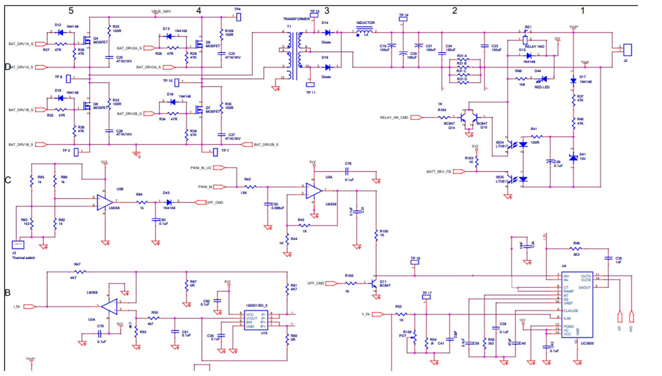
We are using UC3825DWTR in a DC-DC converter. The converter consists of MOSFETs full bridge operating from 380V DC feeding transformer primary. The transformer secondary is center tapped with diode rectifier followed by filter and connected to the load. UC3825 is on the primary side of the converter.
The UC3825 is used in the voltage mode with pins 6 (CT) and 7 (Ramp) shorted. Oscillator is set to about 80kHz with RT 1.5k Ohm and CT 10nF. Pin 8 (Soft start) has a 100nF capacitor to Ground. Pin 9 (ILIM) is shorted to GND. Feedback is connected to pin 1(INV) through a 1k Ohm resistor. Variable reference is connected to pin 2 (NI) from the output of an Op-Amp. A compensation network consisting of a resistor 3.3k Ohm in series with capacitor 100nF is connected between pins 1 and 3.
To begin with, we started testing in the open loop. For this pins 1 and 3 are shorted to each other so that the Error Amplifier (EA) acts as a unity gain voltage follower and the reference to pin 2 is varied from 0V.
As per my understanding, when the EA output rises above ramp valley (about 1.2V) on pin 7, there should be PWM outputs on pins 11 and 14 (OutA, OutB).
The observation are:
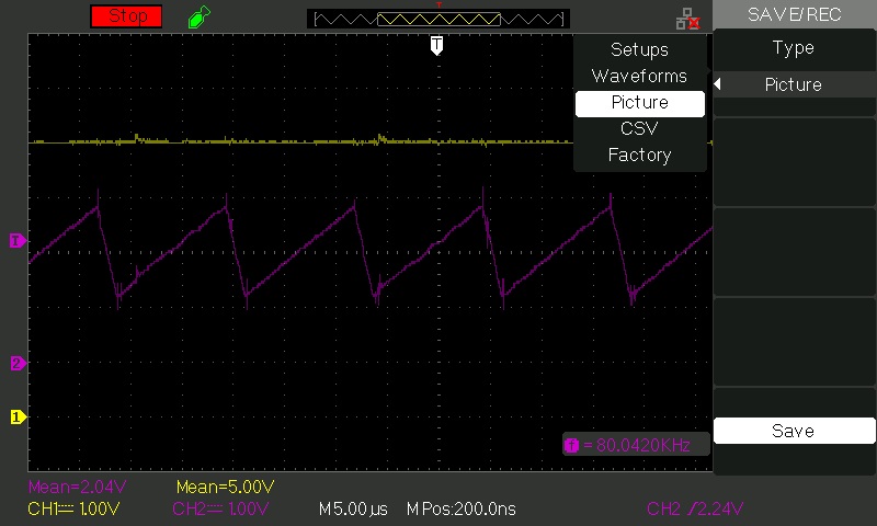
1) There are no PWM outputs even when the EA output has risen above ramp valley on pin 7. There are no PWM outputs for EA output up to about 2.4V. Please see the waveforms below.
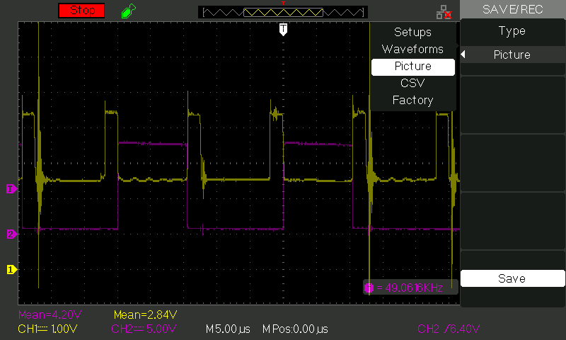
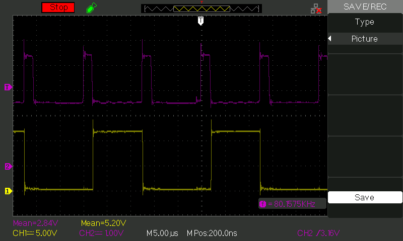
2) When the EA output is increased further above 2.4V, PWM pulses start to appear. However, the pulse widths are not stable i.e. the pulse widths of successive pulses are much different for the same EA output. E.g. as in the waveform below, the pulse widths of successive pulses are about 0.5us and 3.8us.
Can you help to analyze and resolve the problem?
Please see the waveforms below. Since we only have a 2 channel oscilloscope, we could capture only 2 waveforms at a time. The waveforms are under same operating conditions.
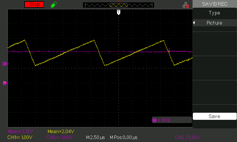
CH1: pin7 (Ramp) CH2: pin3 (EA output)
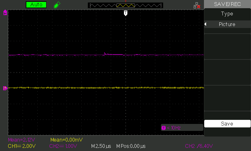
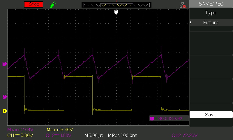
CH1: pin14 (OutB) CH2: pin3 (EA output)
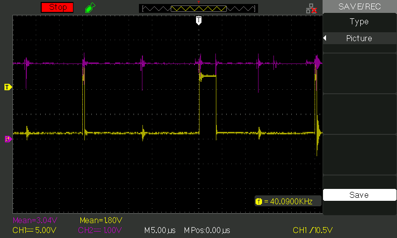
CH1: pin14 (OutB) CH2: pin3 (EA output)