This thread has been locked.

If you have a related question, please click the "Ask a related question" button in the top right corner. The newly created question will be automatically linked to this question.

TPS7A03: Questions on TPS7A03

Part Number: TPS7A03

Hi,

I have some question for calculate accuracy of regulation voltage on TPS7A03, please see my method for calculation below,

*1. I try to calculate voltage regulation in worse case of LDO. By my condition is,

1)      TPS7A0333
2)      VIN: 3.6V
3)      VOUT: 3.3V
4)      Maximum Current: 20mA
5)      Temperature Operation: -40 to 70˚C

Method:
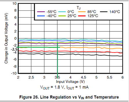
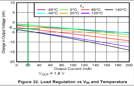
VOUT (worse case) = 3.3V + (Nominal acc (-1%) of 3.3V + Acc over temp (-1.5%) of 3.3V + Line Regulation (-2.5mV) + Load Regulation (-3mV) )

VOUT (worse case) = 3.3V + (-2.5%(3.3) + (-5.5mV)) = 3.3V + (-0.0825V-0.0055V) = 3.3V - 0.088V

VOUT (worse case) = 3.212V

So, for above method calculation of output voltage worse case, this is OK? Or have suitable calculation method? please suggest us.


Note:  Line Regulation choose from graph Line Reg vs VIN and temp.
From your data sheet not have VOUT 3.3V I max 20mA so select VOUT 1.8V and IOUT 1mA.
Have you graph or spec VOUT 3.3 and maximum current 20mA?

Load regulation choose from graph Load Reg vs VIN and temp
From your data sheet not have VOUT 3.3V so I select VOUT 1.8V
Have you graph or spec VOUT 3.3?


 *2.
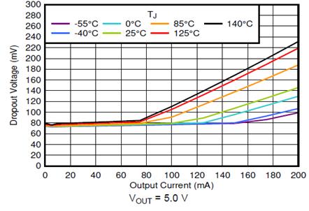
I notice dropout voltage in your spec from data sheet, I would like to confirm for my understanding it matches to your data sheet, please see example below,

Refer for condition from above but change

A)      VIN = 3.6V, V dropout will get around 0.075V. So, this it mean LDO will regulation from voltage input 3.525V

B)       VIM = 3.3V, V dropout will get around 0.075V.  So, this it mean LDO will regulation from voltage input 3.225V,  that is effect with VOUT worse case
Refer from calculation method above,
VOUT (worse case) = 3.225 - 0.088V= 3.137V, this voltage is regulation from VIN 3.3V.

For example above this it, right?


Please let us know

Thanks and best regards,
M.HATTORI.


  • Hello,

    What you are describing is the DC Regulation Band of the power converter (here a linear regulator).  The regulation band is composed of the following elements.  If you are using remote sense lines then there will be a +IR Drop in the Positive Tolerance section as well.

    From this, you need to add any IR drop to your load in your first equation.  As the maximum load current is 200 mA for the TPS7A03, and trace impedance is low, this will be a small value (like the line regulation and load regulation numbers).  IR drop will be larger if you are sending this power across a harness.  The equation should also remove the accuracy tolerance at room temperature because that is redundant with the tolerance across temperature.  It should look like this:

    VOUT (worse case) = 3.3V + (Nominal acc (-1%) of 3.3V IR Drop + Acc over temp (-1.5%) of 3.3V + Line Regulation (-2.5mV) + Load Regulation (-3mV) )

    Now keep in mind that this does not include any transient analysis.  If you have line transients or load transients, they will stack on top of this in accordance with the datasheet specifications.  If your line and load are relatively steady state then there is nothing further to add to this regulation band.

    We only have the test data you are pointing to, not for 3.3V output.  I would use the test data that you have pointed to for the line regulation and load regulation analysis.  But for line regulation I would choose 2.1V instead of 3.6V because 2.1V is 300mV higher than 1.8V, similar to your conditions.  Still, it does not really change your result.

    Question 2 regarding dropout: With 75mV of dropout required, this means that you need Vin to be at least 75mV higher than Vout to stay outside of dropout.  So if Vout is 3.3V, then Vin must be 3.3+0.075 = 3.375V or higher.  If Vout tolerance is +3%: Vin > (Vout*1.03)+75mV = (3.3*1.03)+75mV => Vin > 3.474V.

    Thanks,

    - Stephen

  • Hello Stephen,

    I didn't see the IR drop on the data sheet of TPS7A03, please shared position of voltage IR drop on the data sheet?  

    Or if this need to calculate, please explain how to calculate?

    Best regard,

    Nonthaphat 

  • Hi Nonthaphat,

    The IR drop would not be on the datasheet, it is a function of the board resistance times the load current.  Altium, Cadence and Mentor all have built in tools to run a post layout simulation which will give you this information.  If your load is very small, like 20 mA, then you would need high resistance just to obtain a small drop and you can likely neglect this term in the equation.

    Thanks,

    - Stephen

  • Hello Stephen,

    Thank you for your suggest. And I have additional question, please see below,

    For LDO, I use part number TPS7A0333 this output voltage will regulate to 3.3V. 

    So, if  I supply input voltage 3.3V to 2V ,

    refer from your calculation negative tolerance method is setpoint (3.3V to 2V) - IR Drop (neglect, load 20mA is small) - acc over temp - acc line regulation - acc load regulation - Voltage dropout  

    Did I shoud add dropout voltage into the method?


    Best regard,

    Nonthaphat Phatwong

  • Hi Nonthaphat,

    Once the device is in dropout it cannot regulate the output.  So the output voltage would simply be Vin - Vdropout = Vout. 

    Linear regulators are typically used to take a higher voltage and down convert it to a lower voltage.  If you need to regulate to 3.3V on the output, but your input is 2V-3.3V, you may wish to use a switching converter to regulate to 3.3V under all Vin conditions. 

    Thanks,

    - Stephen