This thread has been locked.

If you have a related question, please click the "Ask a related question" button in the top right corner. The newly created question will be automatically linked to this question.

TPS53319: TPS53319 startup glitch at 45C ambient

Part Number: TPS53319

Hi TI experts,

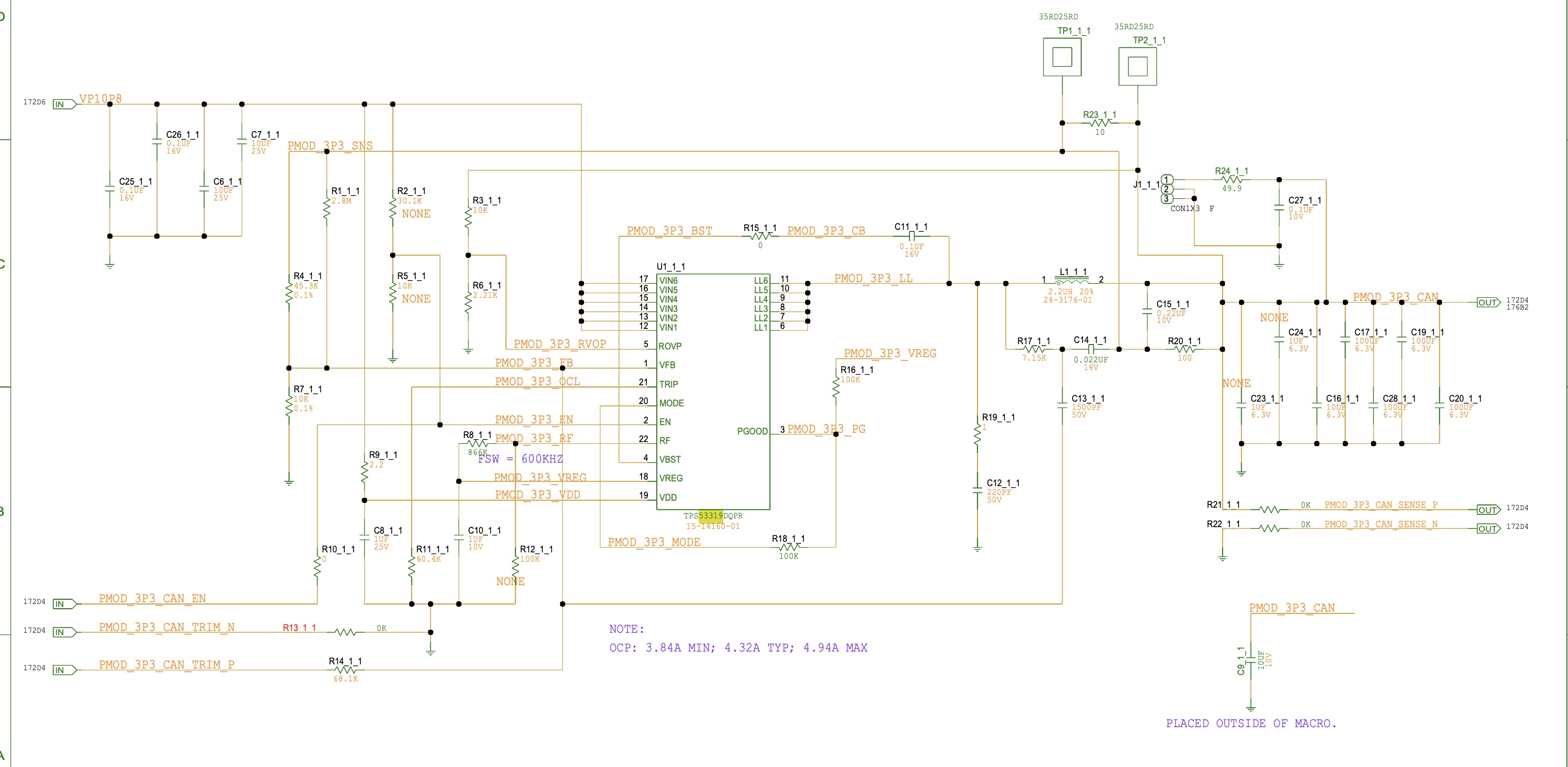
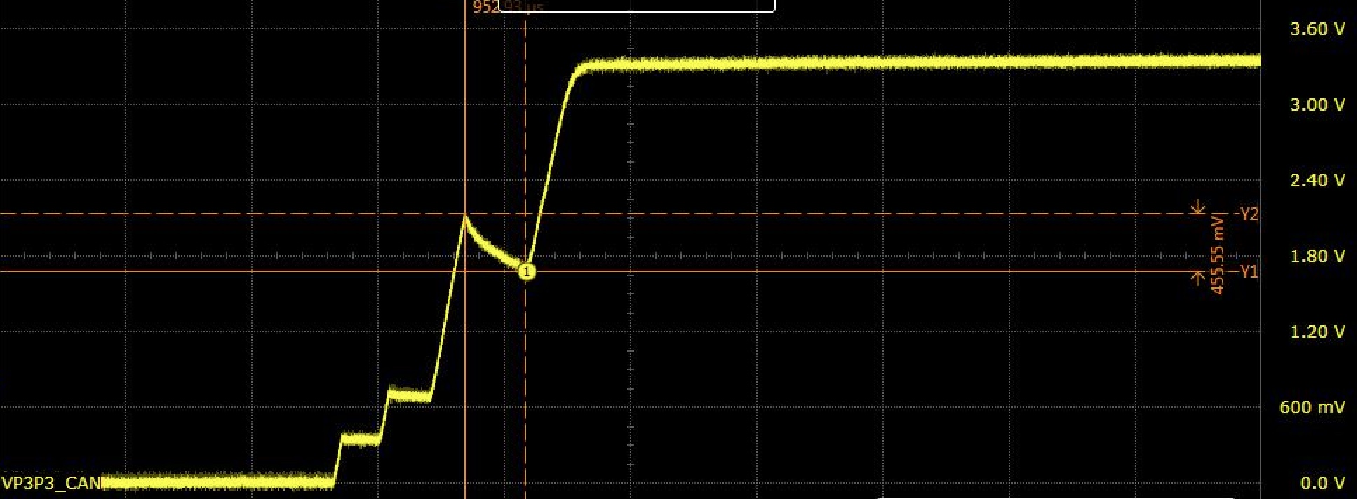
i used TPS53319 to convert 11V to 3.3V/10A. Tested transient/stability/ripple/startup/shutdown waveforms at 25C, all looks good. 

But at 45C, observed 3.3V voltage glitches at ramping up. Planing to probe EN/DIDT/VOUT waveforms at 45C for analysis, but apart from that, is there anything else we can check? Or any idea about this issue?

Please advise.

Thanks.

  •  

    I do not see a time-scale on your oscilloscope waveform, or the resulting pauses between switching.

    What is the MODE resistor value set to? And is it connected to PGOOD or shorted to ground?

    What is the switching frequency?

    What is the output capacitor configuration?  It is all ceramic or a mix of ceramic and electrolytic?

    Is there an external R-C-C ripple injection circuit used with an R-C across the inductor capacitively coupled to the FB node?

    If so, what are the values of the RCC ripple injection?

  • Hi Peter,

    Time scale is 2ms/div.

    Attached the schematic.

    Total cap is 600uF MLCC before DC biased.

    Thanks.

  • FYI. TRIP resistor R11_1_1 has been changed to 121k on board.

  •  

    A couple of things came out of reviewing the schematic.

    1) The time-constant of the ripple injection circuit (1.5nF driving the feedback divider of 10k and 45.3k) - 13kHz is higher than the L-C resonance time-constant of 4.4kHz.  That can cause the output to oscillate when the reference voltage is increasing, which can cause the start-up to burst.

    2) The ripple injection of about 25mV appears to be higher than is needed for the 3.3V output with 600uF bypass capacitance.

    To help improve both of these:

    1) Increase C13 from 1.5nF to 4.7nF

    This will reduce the frequency of the ripple injection down to the L-C resonance, which will help improve the stability when the reference voltage is changing, such as during soft-start.

    2) Increase C14 from 22nF to 47nF

    This will reduce the amplitude of the ripple injection and prevent the increase in C13 from loading the ripple injection node more by keeping a 10:1 ratio between C14 and C13.

    Also check the EN pin, since that input is coming from an external circuit, and make sure R2 and R5 are not installed so that loading on the input can't pull EN low and trigger a shut-down.