This thread has been locked.

If you have a related question, please click the "Ask a related question" button in the top right corner. The newly created question will be automatically linked to this question.

TPS1HA08-Q1: [Inquiry] About SNS output current of TPS1HA08CQPWPRQ1

Part Number: TPS1HA08-Q1
Other Parts Discussed in Thread: TPS1H100-Q1, HSS-MOTHERBOARDEVM

Always I am indebted.

My name is Mitsubishi Electric engineering Tanabe.

I have a question about the subject.

Currently, we are confirming the function of TPS1HA08CQPWPRQ1 on your test board.

Below, there are some differences from the values described in the data sheet.

Could you please answer what the factors are?
Power supply voltage: VBB = 15V
Terminal processing: DIA_EN = 5V, SEL1 = SEL2 = 0 (current sensing mode)
Output current: Iout = 1A~2A
result
SNS terminal current
Iout = 0.5A Isns = 0.137mA
Iout = 1A Isns = 0.271mA
Iout = 1.5A Isns = 0.406mA
Iout = 2A Isns = 0.541mA
Therefore, the value of Ksns is 4600 on the data sheet, but it is about 3700.
Are the datasheet values correct? What are the factors?
  • Hello Tanabe-san,

    The KCL value that you see in the datasheet is the base number. The actual output sense current on the SNS pin will need to have the accuracy numbers below accounted into the calculation:

    The TPS1HA08-Q1 is an 8mΩ part that is meant to higher load currents up to 10A. With the lower load currents such as 500mA (you would use the 300mA number above in this case) you will have a decreased accuracy.

    Question: How are you measuring the currents that you provide and what is the value (and tolerance %) of the resistor connected to SNS?

    The way that the SNS current is measured in design is to convert it to a voltage with a resistor on SNS and have the voltage as an input signal to a microcontroller’s ADC. This means that leakage of the ADC and tolerance of the resistor will be factors here.

    Let’s say your load current is 500mA and you have a 1kΩ ±5% tolerance resistor on your SNS pin. This would correspond to ±12% sense accuracy from the table above. This means that the actual current coming out of the SNS pin could be as low as 95.7µA (440mA/4600) and as high as 121.7µA (560mA/4600). With the ±5% resistor tolerance on the 1kΩ resistor this would correspond to an ADC reading as low as 90mV and as high as 127.8mV. ADC leakage/accuracy/resolution will also play a role here.

    The important thing to know here is that if your load current allows you should use a higher RON device in order to get high current sense accuracies at lower load currents. The TPS1H100-Q1, for example, has the following accuracy numbers:

    Higher RON parts will also be a better option as far as price is concerned.

  • Always I am indebted.

    I will answer below.

    The TPS1HA08-Q1 is an 8mΩ part that is meant to higher load currents up to 10A. With the lower load currents such as 500mA (you would use the 300mA number above in this case) you will have a decreased accuracy.

    ⇒I understand that 1A, 1.5A and 2A are not in the ± 5% range.

     For example, if it is 1A, it will be in the range of 0.206 to 0.227mA.

    Question: How are you measuring the currents that you provide and what is the value (and tolerance %) of the resistor connected to SNS?

    ⇒The voltage across the resistor of 1kΩ ± 5% was measured on the SNS pin.

     I also measured the current flowing directly through the resistor of the SNS terminal using an ammeter.

     The value at that time was as follows.

     Iout = 1A  Vsns=0.271V、Isns = 0.271mA
     Iout = 1.5A Vsns=0.406V、 Isns = 0.406mA
     Iout = 2A Vsns=0.541V、 Isns = 0.541mA
    Even if you look at the MAX values of resistance error and SNS current error, they are out of the results.
    I also considered the flow of current into other circuits, but even if Iout is changed, Isns is constantly changing at around 3700 KSNS, so I think it is the state inside the IC.
    This design does not require low current detection of about 500mA, but requires detection in the 1A to 10A range, so an error of 5% described in the data sheet
    We are considering the resistance error of connecting to the SNS terminal.
    Would you please check the cause again?

  • Hello Tanabe-san,

    Thanks for the detailed response.

    For reference here would you be able to post a screenshot of how your  current sense output looks on the SNS pin output? Is there a filtering capacitor on the input of the ADC? 

    If you are able to completely disconnect the ADC (or put that pin as high impedance via the microcontroller) are you still getting the same results?

    Also, just to make sure, when you measure the output current that you are comparing the SNS current to how are you measuring this? I would recommend having a hall effect sensor probe on the output of the high side switch or an ammeter connected in series with the output in order to eliminate any possibility of instrumentation error.

    You should be getting within specification readings here. We are able to verify that the current ratio is valid using the https://www.ti.com/tool/HSS-MOTHERBOARDEVM 

    We just need to find out the difference between the EVM setup and your application. 

    Also- one last note. When you are testing these different current values are you using an electronic load? Electronic loads in constant current modes are known to interfere with the current sense/limit circuitry of the high side switch. If you are using an electronic load would you be able to change to a discrete power resistor and rerun the test?

  • Always I am indebted


    I will answer.


    (1) Measurement is performed without connecting anything beyond the SNS pin.

    The same result is obtained in that case.


    (2) The output current is measured by connecting an ammeter in series with the output.


    (3)  I am using https://www.ti.com/tool/HSS-MOTHERBOARDEVM.

     It will be the result of the measurement.


    Could you please confirm and tell us the factors again?

  • Tanabe-san,

    Just to follow-up on the last question- are you using an electronic load to test this or are you using a discrete component like a power resistor?

  • Always I am indebted.
    We are using an electronic load.
    Will it affect you?

    For electronic load, I confirmed both constant current mode and constant resistance mode,
    The result was similar.

  • Tanabe-san,

    Electronic loads (especially in constant current modes) will many times interfere with the current mirror of the high side switch. Would you be able to use a discrete resistor on the output as a test to make sure this is not the case with your application?

  • Always I am indebted.
    I did it with a discrete resistor, but the result did not change.
    Iout = 1A Isns = 0.271mA
    Iout = 1.5A Isns = 0.406mA
    Iout = 2A Isns = 0.541mA

    I think KSNS is still around 3680-3700.

  • Tanabe-san,

    I have scheduled some time in our local lab to reproduce this issue on the EVM for tomorrow morning (December 10th). I will update you as soon as I get some information on my end. 

  • Hello Tanabe-san,

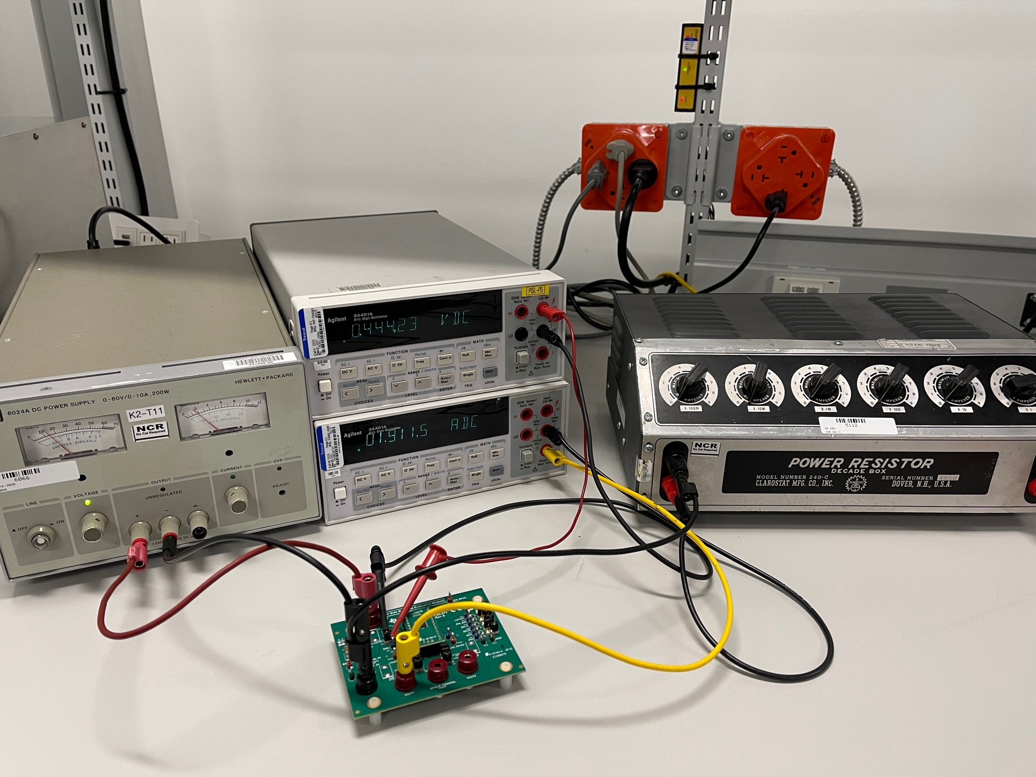
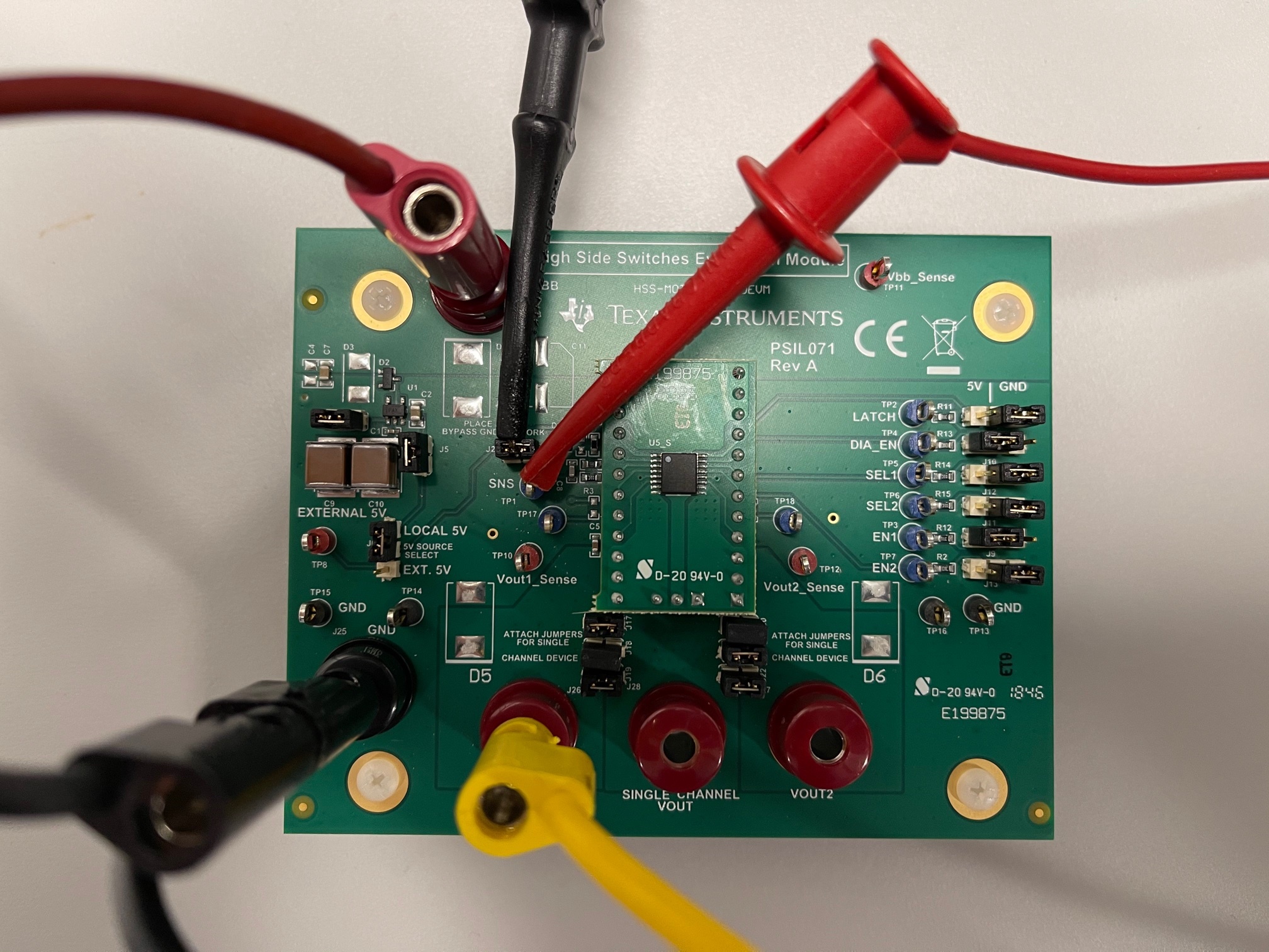
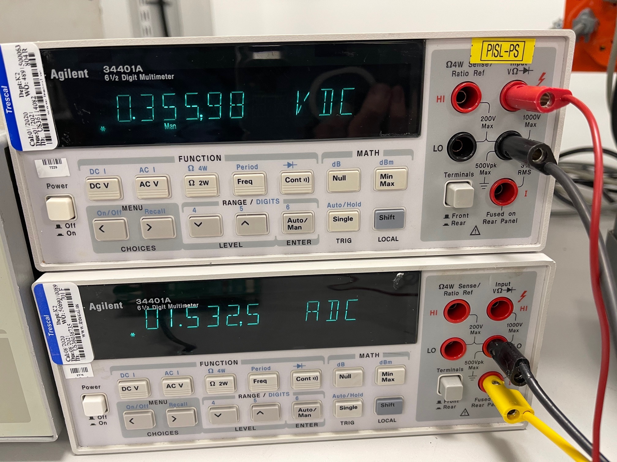
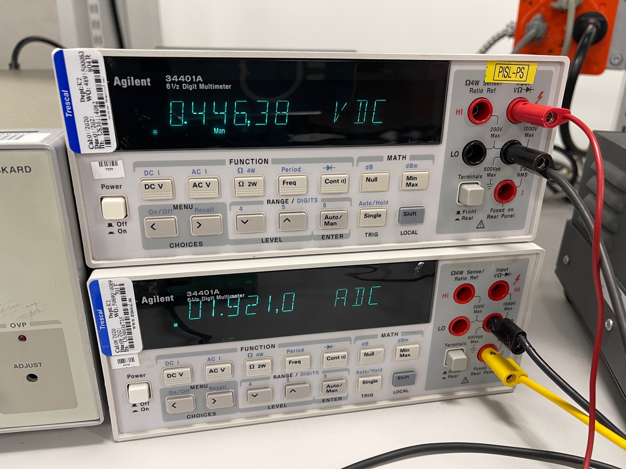
    Thank you for your patience. I was able to run this test in the lab and get expected results in line with the datasheet numbers. I connected the TPS1HA08-Q1  to an attached daughter card and connected it to the HSS-MOTHERBOARDEVM. I connected the power source to a bench power supply, the output of the TPS1HA08-Q1 to bench multimeter, and the output of the multimeter to a power resistor box.  A bench multimeter was used to measure the voltage over the measured 996Ω sense resistor. See the test setup below:

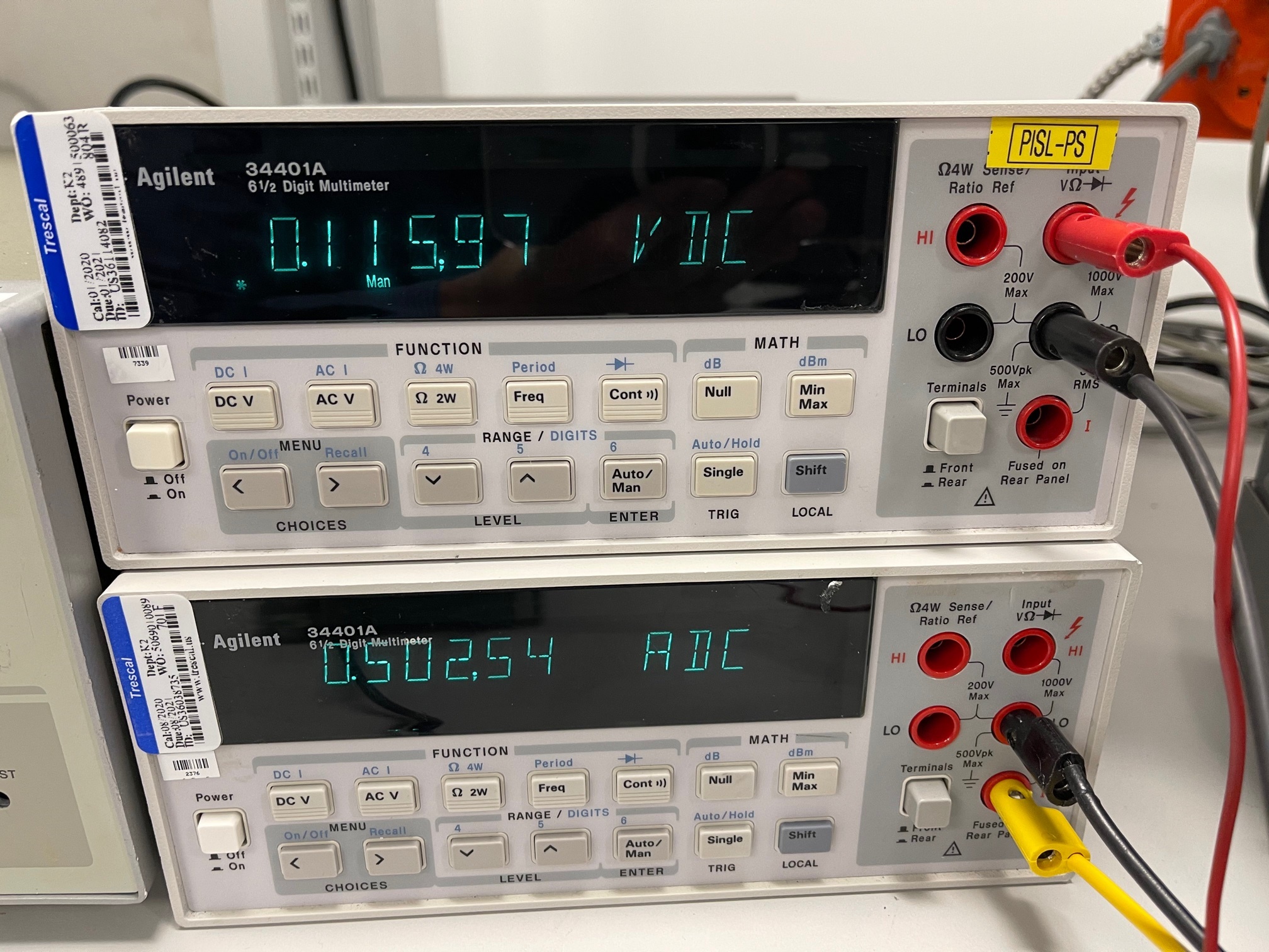
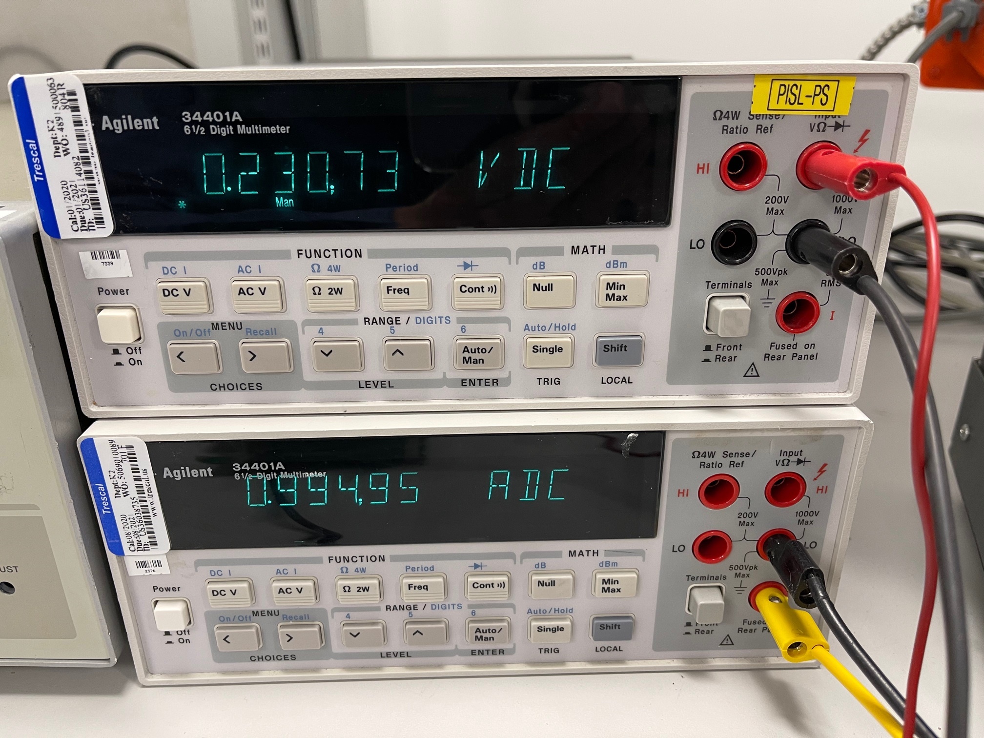
    I ran the device at 500mA, 1A, 1.5A, and 1.92A (the resistor box did not have granularity to go to 2A):

    As you can see from the scope measurements we are getting the following measured values:

    • IOUT = 502mA, ISNS=115uA, Idea ISNS = 109uA, +5.3% accuracy 
    • IOUT = 0.99A, ISNS=230uA, Idea ISNS = 215uA, +6.6% accuracy 
    • IOUT = 1.53A, ISNS=356uA, Idea ISNS = 332uA, +6.8% accuracy 
    • IOUT = 1.92A, ISNS=446uA, Idea ISNS = 417uA, +6.6% accuracy 

    Note that even for the >1A accuracy that is specified as 5% in the datasheet we are getting slightly above. This has to do with the fact that there is a certain amount of series resistance on the multimeter when measuring the output current as well as a certain amount of inductance on the long cables when measuring the voltage/current. The wire inductance will also introduce a certain degree of ringing too that would likely introduce a slight sampling inaccuracy to the multimeter. If this was connected directly to a micrcontroller with just PCB traces the accuracy would fall within the specified limits.

    This being said it appears that my measurements are significantly different compared to the ones that you are doing in the lab. Could you confirm that your test setup is similar to mine?

    Another aspect to note here is where you are measuring the voltage of the SNS resistor. In my setup I put the ground probe on the jumper J24 that connects directly to ground. If there is a large ground loop in the measurement setup an error might be introduced into the system.