This thread has been locked.

If you have a related question, please click the "Ask a related question" button in the top right corner. The newly created question will be automatically linked to this question.

UCC21520: Question with Using Negative Bias with Iso-Bias Power Supplies

Part Number: UCC21520

Hello expert,

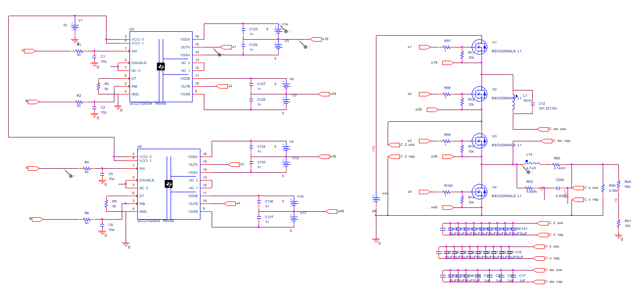
I'm trying to design a Two-Staged Multi-Resonant Multi-Phased Switched-Capacitor Converter with UCC21520.

Based on figure 40 in the data sheet, I decided to use a single-input double-output power supply to implement  negative bias turn-off  for my design.

However, I couldn't decide the voltage value of the VA+ and VA– for the power supplies.

I did some simulation tests with ±5V, ±15V and ±25V for my design using Pspice, and the simulation result showed that when the voltage increased, the inrush current rised during the swiching. 

Also, when the voltage increased, the rising and falling time increased too. Therefore, I prefered to use ±5V in my desgin, but it would increase the risk of unintended turn-on and even shoot-through during switching.

Do you have any suggestion on choosing the voltage of the power supply?

Best regards,

Chih-Sen Ku

  • Hi,

    Can I get more details/literature about what you're trying to do?

    +/-25V and +/-15V are outside of the recommended specs on the driver's output supply.

    Can you show me your schematic?

    Thanks,

    Krystian

  • Hello Krystian,

    I am trying to design a converter that can step down the input voltage from 48V to 12V with high efficiency. 

    The converter is called Two-Staged Multi-Resonant Multi-Phased Switched-Capacitor Converter (MRSCCB).

    The schematic of the single phase MRSCCB converter is shown below.

    There are four MOSFETs in the power stage, so two UCC21520 islated gate drivers are needed for the single phase design.

    Thank you for your help,

    Chih Sen Ku

  • Hi, Ku, I looked at the Infineon mosfet data sheet you are using, and they essentially recommend +10V and 0V. I think if you follow their recommendations, you should achieve good performance in your system. You may want to run our gate driver off a slightly higher voltage to accommodate for losses in the system and get the full 10V applied to the gates of the mosfets. Good luck with your project!