This thread has been locked.

If you have a related question, please click the "Ask a related question" button in the top right corner. The newly created question will be automatically linked to this question.

TPS23754: potential issue, cause output to above 20V

Part Number: TPS23754

Hi experts,

My customer is using TPS23754 in a new design, so far, They found a few of their board output is abnormal after running for a while. the output increased from 12v to above 20v, and can't reover from this damage. attached is their schematic, I've done the comparation with TPS23754EVM-420 EVM and list the difference as below. but honestly, PoE is quite new for me, please kindly suggest if there is potential risk of this design which can cause this problem. appreciate any further test suggestion. thanks.   

  • Hello, 

    This design more closely follows PMP5236  

    The EVM is a 5V sync flyback, and this design is a 12V diode flyback. That is why there are a lot of differences. This is definitely a DCDC problem if you have any experience with DCDC flyback design. 

    My first instinct tells me this has something to do with thermals. If the design is working normally for a long time, and then goes wrong, this is typically due to something heating up and saturating/breaking. Normally, an electrical issue is seen quickly. I could be wrong but that is my guess. 

    Some things to check are:

    - check the thermals of the board. Any components heating up?

    - Check the stability of the board - can they do a load transient (10%-90% with an electronic load). 

    -  How long is a long time running? Are we saying a few minutes, a few hours, a few days?

    - How much load do they have when this happens? Does the system change load and then we see the problem?

    Here are some comments:

    - the Vb bypass capacitor is 1uF, it should be 0.1uF.

    - The output capacitance is placed differently around the inductor. The big electorlytic cap is before the inductor, and the 22uF ceramics are after it -- this is opposite of the reference design. I know theoretically they are the same filter, but the placement of the caps in reference to the feedback line affects the transfer function, so that could be part of it. 

    - The feedback reference divider for the linear regulator (R1845 & R1843) give a voltage of 2.53V. The top end threshold is 2.55V - so it is almost railing at 12V. The thing is that R1845 sets the first pole & zero in the transfer function. So when they changed this and the output capacitance, the feedback transfer function is probably very different. 

    - They should probably populate R1853. 

    If this post answers your question, please indicate so by marking this thread as resolved. Thank you.


    Regards, 


    Michael P.

    Applications Engineer

    Texas Instruments 

  • Micahel,

    Thanks for the suggestion. I'm testing with customer today, below is my feedback.  the main problem is that what may cause the damage of the optocoupler. I verified on customer's board,  changed a new optocoupler can recover. I also checked with local PDS experts. they don't have furhter suggestion. appreciate if you can share some insight about this issue. I also asked my customer to check with opto vendor at the same time. 

    BTW, Could you please suggest a solution to detect this issue? What I can see is the output will increase to above 26V when opto damage  . 

    - check the thermals of the board. Any components heating up?

    [ Yue]: no obvious heart up.

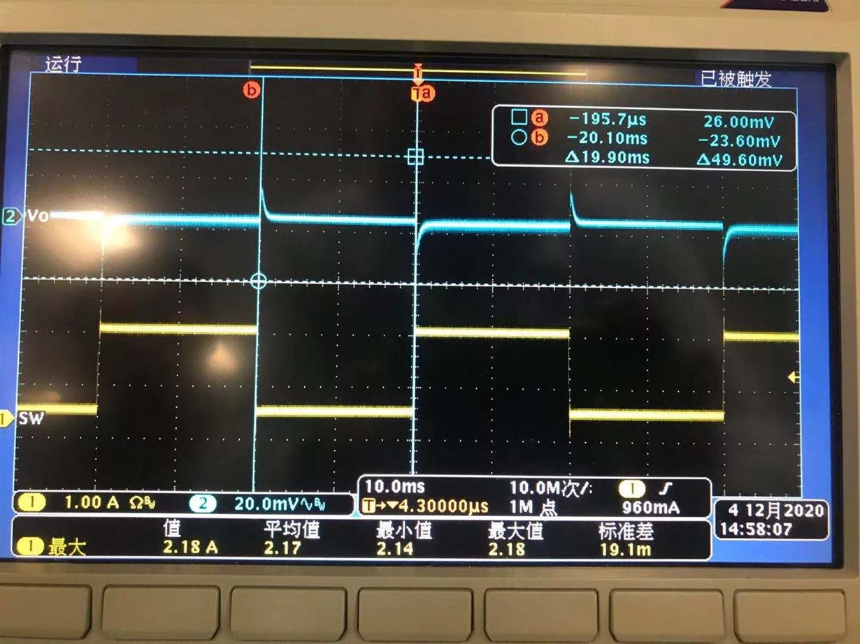
    - Check the stability of the board - can they do a load transient (10%-90% with an electronic load). 

    [Yue] We did this test, the waveform is fine, please see below picture

    -  How long is a long time running? Are we saying a few minutes, a few hours, a few days?

    [Yue] a few days, so far, 4pcs with the same issue was found, they have produce  over 3000pcs 

    - How much load do they have when this happens? Does the system change load and then we see the problem?

    [Yue]1.6A ~1.8A. And no, we keep doing traisent test [from 0.2A to 1.8A] for about one hour, no issue found. 

    About your comments :

    - the Vb bypass capacitor is 1uF, it should be 0.1uF.

    [Yue] : chnaged to 0.1uF

    - The output capacitance is placed differently around the inductor. The big electorlytic cap is before the inductor, and the 22uF ceramics are after it -- this is opposite of the reference design. I know theoretically they are the same filter, but the placement of the caps in reference to the feedback line affects the transfer function, so that could be part of it.

    [Yue] : May modify on next design.  

    - The feedback reference divider for the linear regulator (R1845 & R1843) give a voltage of 2.53V. The top end threshold is 2.55V - so it is almost railing at 12V. The thing is that R1845 sets the first pole & zero in the transfer function. So when they changed this and the output capacitance, the feedback transfer function is probably very different. 

    [Yue]: They tested loop, it is fine. also grardully increase the load to 1.8A, the output is stable 11.86V,  but once up to 1.9A , the output decline to 11.4V and 2A will make output drop to 11.02V . so they may need to further modify loop.  

    - They should probably populate R1853. 

    [Yue]: No, they didn't populate R1853, also there is a 2K resistance connencting to pin1 of optocoupler.

  • Hello Yue,

    Oh i see, so the opto is breaking.

    I checked the thermal ratings for the opto and they seem comparable with what some of reference designs use. 

    Honestly I think it is a reliability issue with optocoupler. I think if there was an issue with the PoE we would see it way sooner than a few days. Additionally, if there was some sort of surge or ESD event, then I would think other parts would get damaged if the optocoupler is damaged.  Since it is such a small number in their manufacturing, it sounds to me like a quality issue.

    If this post answers your question, please indicate so by marking this thread as resolved. Thank you.


    Regards, 


    Michael P.

    Applications Engineer

    Texas Instruments