This thread has been locked.

If you have a related question, please click the "Ask a related question" button in the top right corner. The newly created question will be automatically linked to this question.

TPS7A02: Application suitability of TPS7A02

Part Number: TPS7A02

I am planning to use TPS7A02 for converting a LiPo battery output to 3.3V fixed. Specs for battery are: Type: LiPo; Rated Voltage: 3.7V; Voltage at full charge: 4.1V; Minimum Voltage at which battery will be replaced: 2.8V

The sensor which will be powered consumes 15uA current while in sleep state and periodically wakes up at every 2 sec consuming peak current of 180mA for 10ms. 

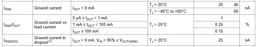
Is TPS7A02 a good choice for this application, will TPS7A02 maintain its low Iq when it is in dropout and consume low Iq in ranges of nA while the battery voltage drops as low as 2.8V.

Thanks!

  • Hi Mayank,

    The TPS7A02 was designed to draw very low current while in dropout as well as in regulation.  This can be found in the EC table within the datasheet:

    Thanks,

    - Stephen

  • Hi Stephen,

    1) Thanks for the clarification. So for the conversion mentioned earlier(3.7V LiPo to 3.3V) TPS7A02 would be a good choice, given at 200mA Iout dropout will be 310mV? Please confirm.

    2) Further, the datasheet mentions that in dropout the transient response will deteriorate. Any indications on much will it suffer for a 3.3V fixed Vout.

    3) I am planning to put capacitors Cin=100uF and Cout=4.7uF, would that be a good design assuming 180mA periodic peak loads for 10ms (every 2 second). Can I increase the Cout to 100uF to improve the transient response or the TPS7A02 can take care of sudden change in Iout.

    Thanks,

    Mayank

  • Hi Mayank,

    1. Correct, the TPS7A02 will be in regulation with 400mV of headroom at 200mA loading.

    2. While in dropout the device is not regulating. It is effectively passing Vin to Vout (with some small drop due to Rds_on * Iout).  The transient response is really just the impact of Cin and Cout, with some impact due to the current limit.  I would add as much Cout as you can to improve load transient performance while in dropout.

    3. To reduce the impact of load transients, you want as much Cout as you can get.  The output voltage deviation during a load transient is dominated by the capacitor equation (I=C*dV/dt) before the feedback loop kicks in to recharge Cout and provide the current.  Make sure your capacitors are ceramic or polymer type capacitors, this will reduce ESR.  Watch the voltage bias effect on ceramics, but ceramics will have lower ESR than polymers.  Larger package ceramics tend to do better with voltage bias effects - an 0805 or so ceramic rated at 16V or 25V might do well here.  Ideally Cin > 10x * Cout to help with inrush, but at Cin = 100uF you are probably safe with any value of Cout that keeps the device stable (22uF max).

    Thanks,

    - Stephen

  • Hi Stephen,

    Thanks for the clarity. I have designed the PCB with a Cin = 100uF Cout = 4.7uF. I have drawn two ground planes, one on top connecting all pins and battery input. Another ground plane is on bottom layer (vias between bottom and top layer ground plane). Apart from this there is an input power plane connecting IN of TPS7A02 and battery connector. Can you please check if this PCB design is good enough for TPS7A02 application.

    Thanks

    Mayank

  • Hi Mayank,

    Your layout looks good.

    Thanks,

    - Stephen

  • HI Stephen,

    Thanks for your help, appreciate it.

    -Mayank