This thread has been locked.

If you have a related question, please click the "Ask a related question" button in the top right corner. The newly created question will be automatically linked to this question.

LM5160-Q1: Problem with simulation result of the fly-buck converter

Part Number: LM5160-Q1
Other Parts Discussed in Thread: LM5160

Hello,

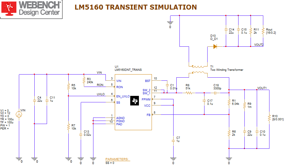
I want to build a flybuck converter with LM5160-Q1. I have done some simulation work and the result shows that the output voltage could be controlled.

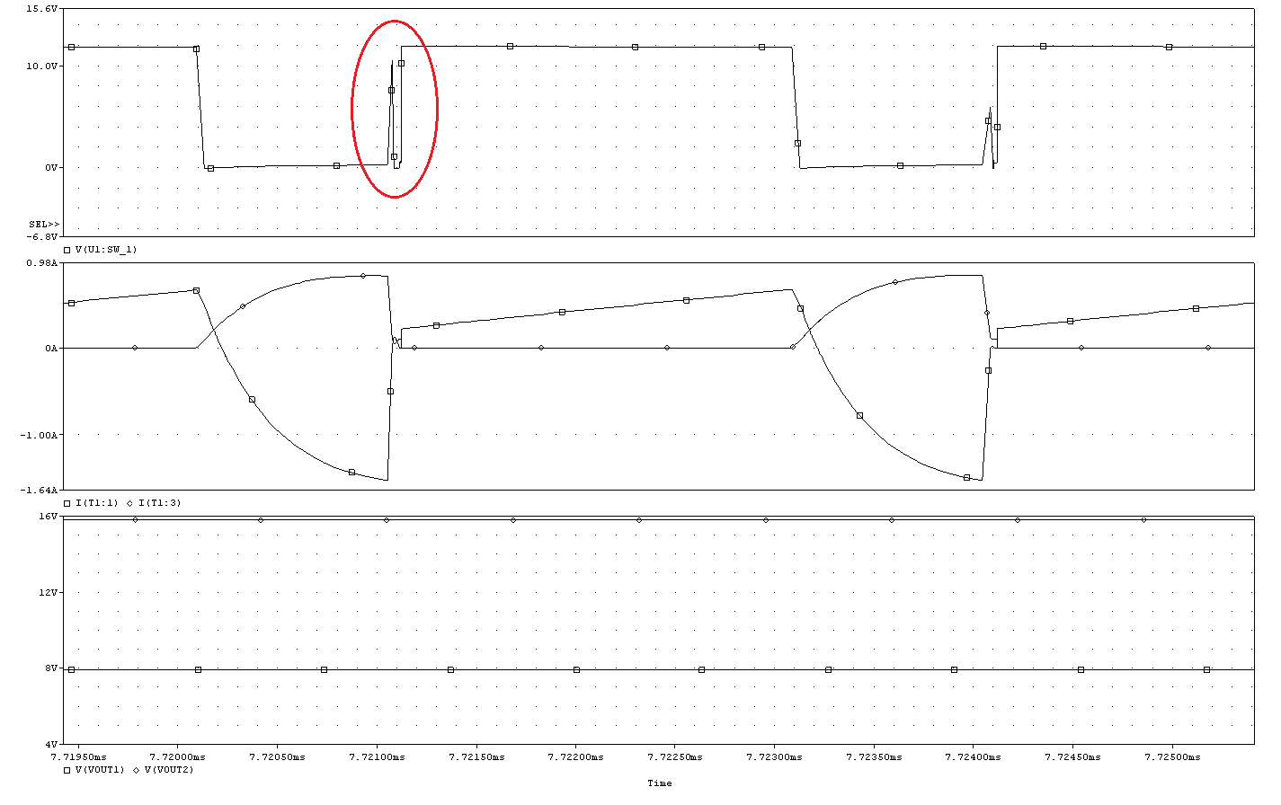
But I notice a minor problem with the waveform of SW node, as indicated by the red circle in the figure shown below. Would you please to explain why there is a spike at rising edge of the waveform? How to get rid of it?

The schematic is shown below.

  • Hello ZD,

    I will need to check with an engineer more familiar with this device. I will get back to you soon.

    Regards, Jason

  • Hi ZD, 

    The inductor current is negative when the low-side FET turns off, so the SW voltage will charge during the deadtime (and possibly show resonant behavior depending on the energy involved). This is expected behavior and can be checked with the EVM.

    Note that you can also use the LM5160 quickstart file to assist with component selection (see product folder for download).

    Regards,

    Tim