This thread has been locked.

If you have a related question, please click the "Ask a related question" button in the top right corner. The newly created question will be automatically linked to this question.

TPS56339: Part fails after a few power input ON/OFF cycles.

Part Number: TPS56339

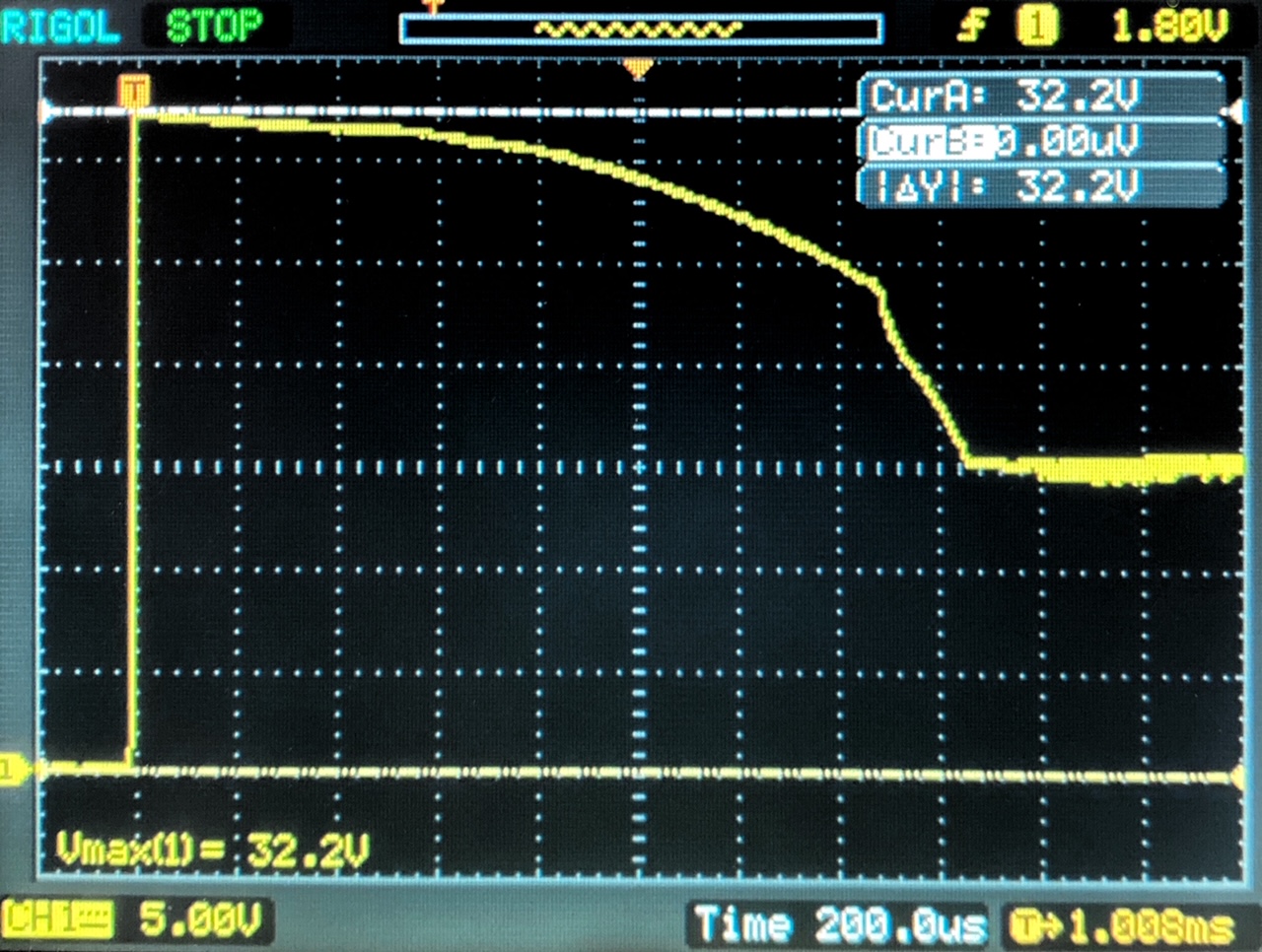
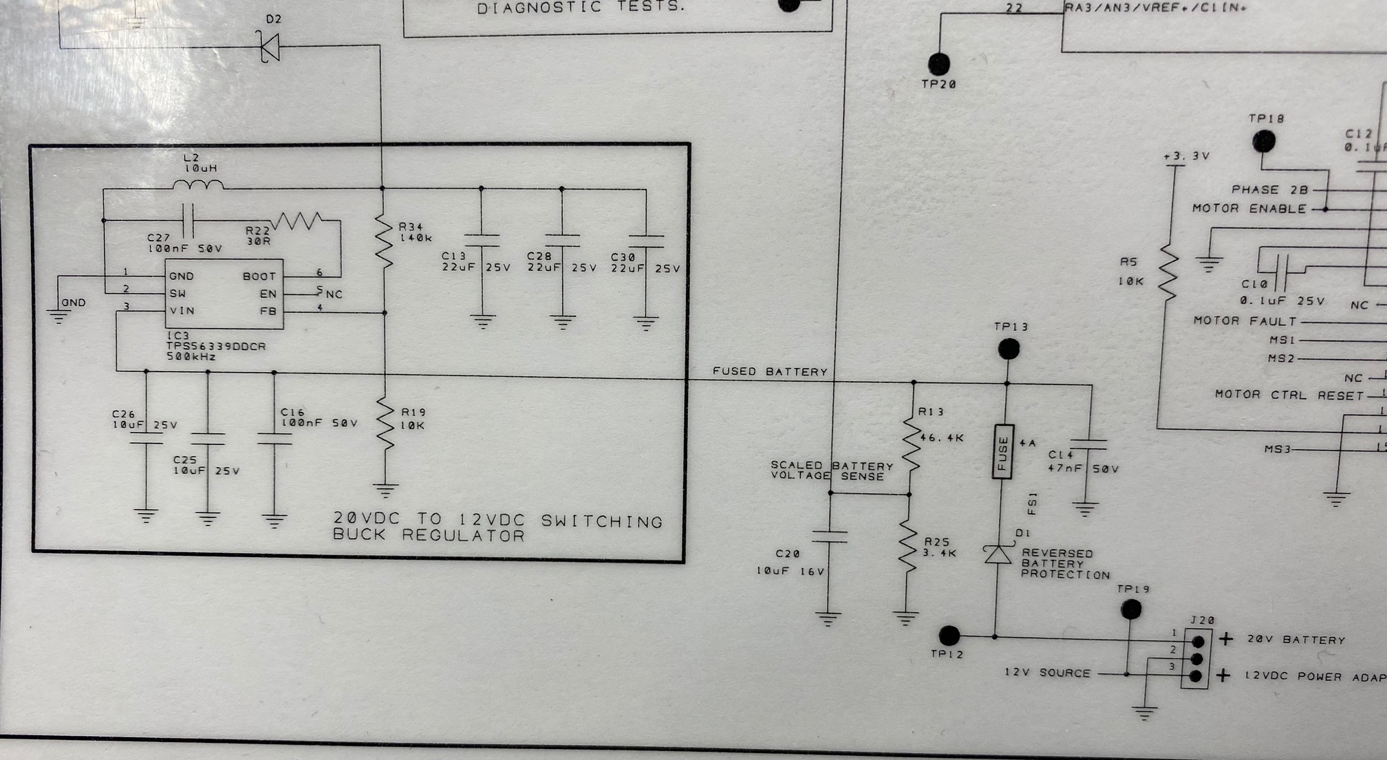
We are using the published reference design with the part numbers called out in the BOM.  Our circuit layout is modeled after your reference design board with the "EN" line floating.  Our design is for 14 to 22 volts input with 12 volts output at 3 amps although the nominal load is only a few hundred mA.  The circuit actually works well when first turned on.  No heated parts, no noise, nice clean 12V output.  The failure comes randomly after a few power-down and power-up cycles (typically within 5 to 10, but sometimes sooner).  Once successfully turned on, it continues to run without a problem.  The power cycles are done with a simple toggle switch in the 20V 3A power adapter input line.  The failure occurs identically when powered from a bench supply with an inline toggle switch.  After the part fails, a resistance check finds a short from Vin to ground. We have the input to the board fused, and the fuse blows so we don't see any burned parts during the failure.  The load on the supply at first turn on is about 20mA.  This increases to about 600mA once the circuit runs ~500mS and boots a micro-controller, and in operation may see an occasional 1.5A load.  It only fails during either the power-down or power up cycle.  We can't tell which because once it fails it current-limits the bench supply on the next turn-on when we have the fuse bypassed.  We are using the recommended inductor from the BOM of the reference design which is a Bourns SDR1307-100ML 10uH 21mOhm.  We have tried other inductors as well with different ratings (5.6uH and 22uH) and had the same failure where it works a few times, or for an extended time when left on, but fails with power cycle (slow normal physical toggle switch OFF for a few seconds and back ON).

Any insights or suggestions would be appreciated.

  • Hi,

    Could you help capture the VIN waveform to check the max voltage ?

    BRs,

    Young

  • I'm a little embarrassed that I hadn't already done that!  I captured the power-up on my scope with the power supply voltage set to 15VDC.  My intention was to start low and gradually build up to the 20 volts it will run at since I knew it would short eventually.  Surprise!  With the power supply set at 15 volts I see a surge at 32V that then settles down to the 15V.  So it looks like that surge/spike is what's killing the regulator IC, but I don't understand where that surge comes from.  If I use the power switch on the power supply to turn the voltage on and off, I don't see the spike.  I suppose the power supply has some kind of soft start?  If I used an inline toggle switch interrupting the positive lead from the power supply, then I see the huge spike???  Anyway - here is the scope frame from the power-up that you asked for and a pic of the section of our schematic for the regulator.  Our actual circuit uses a switch to activate this buck regulator with voltage from a 20 volt battery and it does kill it after a few on/off cycles.  Suggestions??

  • Hi,

    suppose that there is high spike may damage IC, you can try add a large CAP at VIN pin .

    and I find that the withstanding voltage of Cin(C25/26) may be not enough for 20 VIN rails , considering derated value of cap would decrease .

    Also a bead may be helpful before VIN cap for high frequency noise isolation .

    BRs,

    Young

  • Young, Thank you for your comments and suggestions. I ended up putting a 20volt TVS diode on the input to the buck regulator. It turns on and clips the transient at 23.6 volts, well within the 26 volt max of the regulator IC. I also changed the MLCC caps on the input to 35 volt caps instead of the suggested 25 volt ones to leave a little room for derating. Rigorous testing shows good results.
  • Hi ,

    Glad to hear that . 

    Please let us know if there is any further support needed . 

    BRs,

    Young