This thread has been locked.

If you have a related question, please click the "Ask a related question" button in the top right corner. The newly created question will be automatically linked to this question.

LMG3410R050: LLC Resonant Converter simulation problems

Part Number: LMG3410R050

Dear all, good morning.

I am trying to simulate a resonant converter using Test_LMG3410_BUCK design example as starting point, just replacing  LMG3410R150 with the LMG3410R050. Apart from that, the switching frequency was changed to 500kHz and the power-side voltage to 50V, but the rest of the circuit remains unaltered.

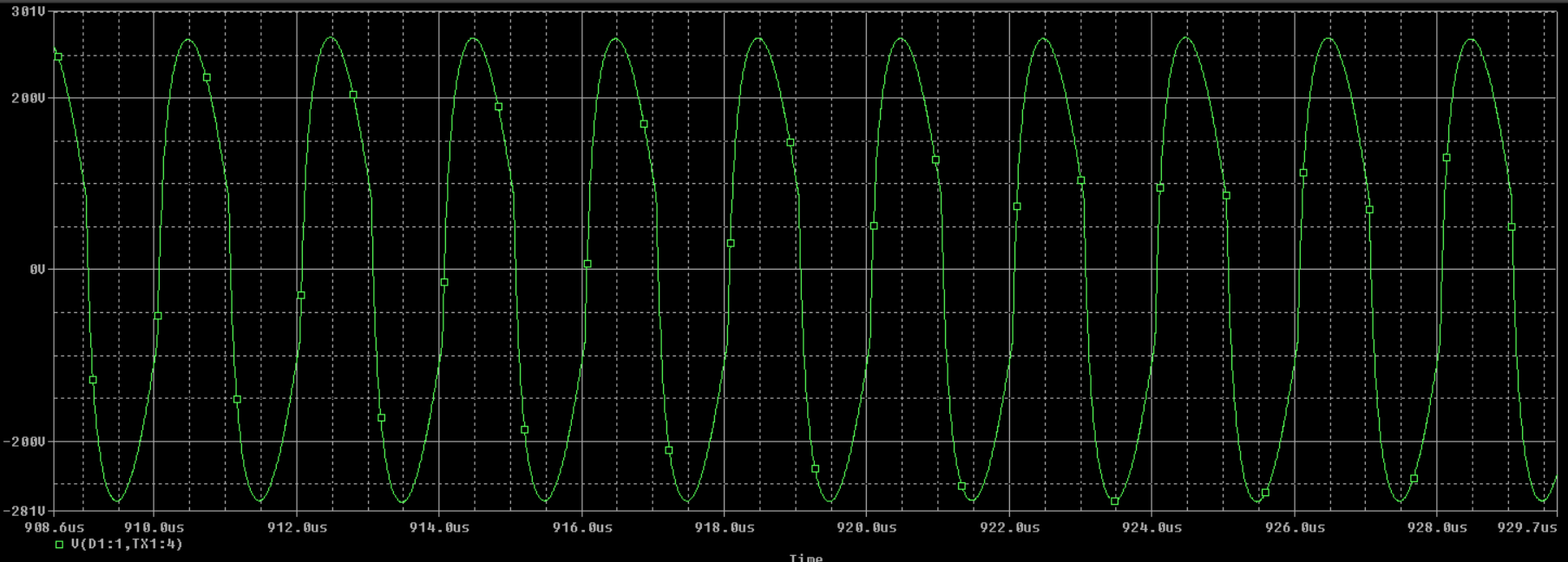
When I test the half-bridge with no load or resistive one, I obtain the desired square waveform. However, when I connect the resonant circuit, the output waveform just do not make sense.

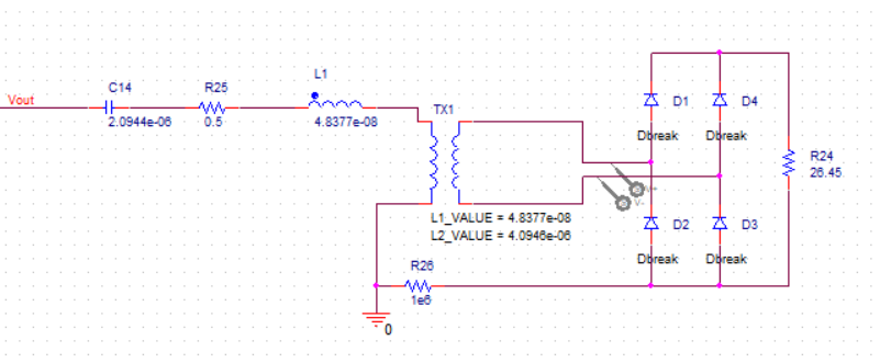
Doing some desperate trials, I realize that including an isolated voltage source (as shown in the following picture) makes the system work as desired. Nevertheless, it seems that including this component is not right as I cannot analyze the effects produced by the resonant circuit in the switches.

It is important to say that the resonant circuit was also tested with sinusoidal and square-wave voltage source, and it is working as expected.

Any suggestion regarding this issue will be highly appreciated! Thank you all in advance.

  • Hello Leandro,

    Thanks for contacting us! Would you able to share the waveform you have without the isolated voltage source, or/and the simulation files? Thanks!

    Regards,

  • Dear Yichi Zhang, thank you for your reply!

    This is the project with the isolated voltage source:

    proj_with_isov.zip

    This is the project without the isolated voltage source:

    proj_without_isov.zip

    This is the waveform in the secondary of the transformer without the isolated voltage source:

    On the contrary, this is the waveform in the same point with the isolated voltage source:

    This is a zoom of the previous waveform:

    Thank you very much for taking the time to review my question. Let me know if you need further clarifications. Once again, thank you very much!!!

  • Hi Leandro,

    The one without the isolated voltage source goes to protection because the current is above the over current protection threshold: you can see it by probing the current at the switch node, and also the Fault signal. The one with the isolated voltage source, the SPICE treated the current going into the iso source is zero (I think), and it does not trigger the OCP function and device can work properly.

    For the one without the iso voltage source to work, you need to increase the inductance so the current is smaller. As long as the current is below ~50A (threshold for R050 device from datasheet), you should see device operating correctly.

    Please let me know if you have further questions.

    Regards,

  • Dear Yichi Zhang,

    Thank you very much for your time and clarification. I will closely check your observations! Thank you!!