This thread has been locked.

If you have a related question, please click the "Ask a related question" button in the top right corner. The newly created question will be automatically linked to this question.

LM5085: Inductor, MOSFET and Diode part review in step down regulator

Part Number: LM5085
Other Parts Discussed in Thread: , LM5005

Hello all,

We have a system with the following specs:

  • Vin typical of 48V, max of 72V
  • Vout of 4V going to a GSM module
  • Iout in idle scenario is 40 mA
  • Iout average when communicating 600 mA
  • Iout peak of 2A for a period of 577 us with an interval of 4.6 ms. Max drooping of Vout can be 0.3V at this point.
  • Cost sensitive application

With this in mind we've chosen the following parts:

  • Inductor BWVS00606045470M00 with 47 uH, 1.2A current rating and 1.9A saturation current
  • MOSFET PXP400-100QSJ with typical Rds ON as 270 mOhm, max of 400 mOhm, Ids continuous of 1.4A, total gate charge of 10.1 nC (max 15.2 nC), 100V Vds max
  • Diode SL110PL-TP with 600 mV Vf, 100V max Vr, 0.5 mA Ir

Would these components be adequate for this design with enough? Thanks, Prithvi

  • Hi Privthi,

    LM5085 seems good for this application, I ran a quick WEBENCH design for 48V-72Vin to 4V 2A out and the load transient seems good.

    Your 47µH inductor saturates at 1.9A though, the inductor could saturate during your load transient to 2A. I suggest an inductor with saturation current larger than your peak output current.

    You can run WEBENCH simulation with your BOM and should also try it out on a LM5085EVAL EVM board.

    Let me know if you have further questions,

    -Orlando

  • Thanks Orlando. Few more questions following your answer:

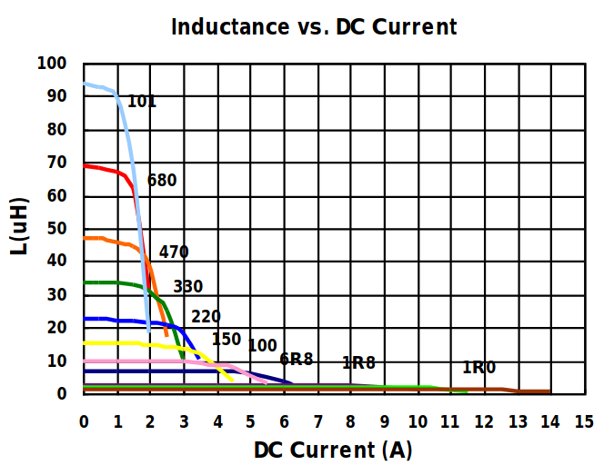
    - For the inductor since a 47uH one is chosen which is more than the Webench, so even with 2A current plus switching current, it'll still have enough inductance, right based on the graph below?

    - Is it possible to use a custom inductor, MOSFET and diode in Webench? I can't seem to figure out how.

    - Also as in this question we'll also be directly powering a GSM module, so the buck regulator will go into a "power bank" of capacitors, say one 100uF tantalum and one 10uF ceramic. Can the input capacitance of GSM module also be the output capacitance of LM5085 and in which order?

    - Because of this "power bank" of capacitors, how would the values of Rr, Cr and Cac for ripple rejection change?

    Thanks, Prithvi

  • Hi Prithvi,

    The sat curve seems tight for a 2A load, especially as (1) the saturation point decreases at hot and (2) some margin is required for current limit. You can choose the inductance based on a 30-40% ripple current.

    In terms of Cout, the downstream capacitance adds to the total output capacitance as it's all on the same rail effectively. If you're using type-3 ripple injection, then the values are not affected by this. Just choose the components to give sufficient triangular ripple voltage at FB (based on the square-wave voltage across the inductor developing a triangular voltage on Cc, which is then AC coupled to FB).

    As an aside, note that we have converters (with integrated FET) for this application, e.g. LM5005 75V/2.5A.

    Regards,

    Tim