This thread has been locked.

If you have a related question, please click the "Ask a related question" button in the top right corner. The newly created question will be automatically linked to this question.

TPS53315: Design review

Part Number: TPS53315
Other Parts Discussed in Thread: TPS25982, TPS22959

Hi,

Attached is my current schematics for TPS53315. My Vin=12V, Vout=5V and Iout=12A.

I am currently facing power fluctuation issue during SATA HDD hotplug which has 5V connected to it. Can you please let me know what will be the IOCP fixed for RTRIP=68.1kohm. Considering the ITRIP=10uA and RDS=7mohm, i got IOCP=13.26A. Is the calculation correct.Design10.pdf

  • I calculated around 13.5A for current limit.     

    The OC protection is cycle by cycle until the UVP is triggered. 

    Once the UVP is triggered, the device will hiccup and restart.  

    Can you take an oscope pic of the output voltage during the hot plug event, trigger on the falling edge of Vout. 

    Also, Can take an oscope pic of the inductor current using a current probe during the hot plug.

    Does the output voltage drop by 30%?

    What is the maximum input capacitance of the 5V rail of the SATA HDD?

    Can you share board layout image?

    Also, can you use a dc load (not the HDD) on the TPS53315 and take a scope pic of Vout and and LL node with about 2us/div

  •    Hi,

    Please find the attached snapshot of board layout, Vout and LL signals. 

    In board the maximum input capacitance of the 5V rail of the SATA HDD is 10uF.

    The waveform snap of the output voltage during the hot plug event is not possible sincethe issue is observed at customer's place.

    Also the issue is observed only in Western Digital HDD.

  • Your waveforms are typical, and do not see any issues.  

    On your schematic I would change C318 from 330nF to 1uF. 

    The layout only has 3 output capacitors and the schematic has 9 capacitors.

    If the hot plug is causing a 0 to 12A output current load step on the supply, 

    I would add more output capacitors.

    Can you replicate the issue by hot plugging a 10uF and 12A load to your board?

    Did your customer send you waveforms or other documentation of the issue.

    Can your customer capture the fluctuation during hot plug?     

    Do other models (not WD) of SATA HDD hot plug without fluctuation?  

    Does changing Rtrip or adding Cout make the issue go away. 

    If hot plugging the HDD to a lab supply, can the current be measured on the oscope.

  • Hi,

    1. Just wanted to know how will the value of C318 impact the surge or fluctuation

    2. Provision for 3 capacitors were provided during initial design stage. But only with 3*47uf capacitors, issue was found even while hot plugging one HDD. Because of surge issue, we have stacked extra 2 capacitors on all three pads. Now we have total 9 capacitors.

    3. Hot plugging one HDD at a time wont cause any fluctuation. Hot plugging 2 device at a time is causing the issue. And the problem is only with WD HDD.

    4. Do you think changing RTRIP will have any impact. Since the maximum load will not be more than 10A. And RTRIP is already set beyond load current limit. 

  • 1)  C318 is the output capacitor for the internal linear regultor (VREG), I recommend a 1uF/6.3V/X5R capacitor.

    VREG is the bias supply for the mosfet drivers and analog control circuits.  For robust operation,

    having a steady output voltage on VREG is important.   During the hot plug maybe there is a noise on the VREG,

    increasing the C on VREG will minimize noise and reduce a potential issue. 

    2), 3)   When you state fluctation during hot plug,  I am not understanding.

      Is the output voltage dropping to zero volts and restarting.   Is  the output voltage drooping by 100mV, 1V, etc?   

     Is the converter have unstable switching with large output voltage ripple?  Is the converter turning off?

    4)  If the output voltage is dropping to zero and restarting,  adding Cout and change Rtrip can help. 

    The effective capacitance of the ceramic capacitor changes with the dc voltage.     

    A 47uf/6.3V at 5V is about 15-20uF depending of size. 

    The schematic and your waveforms show stable operation.        

    I think having a waveform or other data of the hot plug profile of the HDD would be helpful.   

    This is a difficult issue to troubleshoot without pictures.

    Can you replicate the issue by hot plugging a 20uF and 12A load (the equivalent of 2xHDD) to your board? 

    Has the WD HDD SATA  been characterized.     Can you validate that the input of the HDD is 10uF?   

    Can someone hot plug the HDDs to a lab bench supply and measure the current and voltage on the rail?


  • Hi David,

    I will check with my customer whether he can probe the signals.

  •  

     is on leave until early January 2021.  I will mark this thread "Waiting for Customer" while awaiting the customer's response.

  • Hi David,

    This is regarding point 4, you have mentioned that increasing COUT will help. The package of output capacitors on the board is 0805. Currently I have 47uF,10V capacitors on the board. The last higher value available in this package is 100uF. But the voltage of it is 6.3V. 

    It is better to use capacitors with rated voltage 6.3V or 10V. 

    Please suggest.

  •  

    Due to the DC bias effects reducing the effective capacitance, with a 5V output, you are likely better off using the 47uF 10V capacitors than 100uF 6.3V capacitors.

    Regarding the hot-plug issue.  The problem is likely that there is a direct capacitive path from VOUT to FB through the RCC injection (C65, C325) which is directly coupling the dynamic voltage from VOUT dropping to feedback, rather than scaling it down from 5V to 0.6V.

    If VOUT drops by 180mV rapidly, that can force FB down 180mV and trigger under voltage protection.

    Looking at the design, I see a lot of ripple injection, about 72mV (12V to 5V @ 400kH into 1k-Ohm / 100nf)  A lot more than the design really needs.  Here are a couple of things to try:

    1) Just speed up the transient response

    Change R106 from 1k to 4.02k.  The reduced ripple injection will help speed up the transient response to a drop in VOUT, giving the converter more time to bring Vfb back up before the under-voltage protection trips.

    2) If that change alone does not solve the issue, increasing Rtrip might help allow the converter to deliver more current to the output voltage during that recovery, helping it recover faster.

    If the issue is current limit restricting the recovery time, you should see VOUT and VFB drop when the HHD is hot-plugged, and then the VOUT rise back up linearly as the current limit charges the output capacitors at the current limit, then about 1ms later, the converter stop and shut-down the output voltage.

  • Hi James,

    1.Can you please provide me more insight on ripple injection. The current existing value was provided by TI engineer earlier. Could you please let me know the N value for current circuit.

    e2e.ti.com/.../3380159

    2. The TI webench shows a Tantalum capacitor. I have not provided that in my design. Will that cause any major issue.

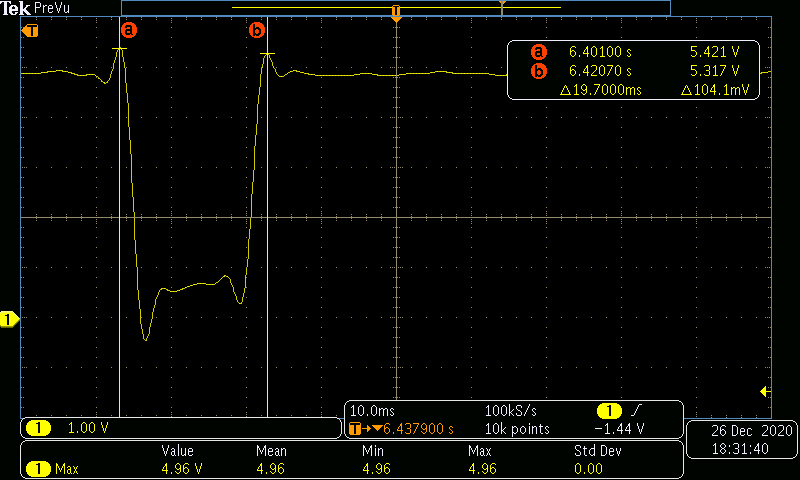
    3. Attached is the waveform of Vout with just 47uf*3 output capacitors. Fluctuation is observed with hot plugging single HDD. This issue is not observed with 47uf*9 capacitors. Just shared the waveform, thinking it might help us to debug the existing issue.

    4. ''In an overcurrent condition, the current to the load exceeds the current to the output capacitor, therefore the output voltage tends to decrease" Can you please explain me the meaning of this sentence in Page 15 of datasheet. Section: 7.3.8

    As per my understanding ,the current to the loads flows through the output capacitor. Hence how can they vary.

    5. Also referring to attached image, what might be reason for this drop. Is it the inrush current?

    6.Does IOCP indicate steady state current or inrush current

  • Hi Shifali N

    You might expect some delay in our responses due to holiday season.

    Thank you very much.

    Regards,

    Ruby

  •  

    The "N" factor is the ratio between the switching frequency and the effective zero-frequency created by the RCC injection at FB and the AC ripple from the output capacitors.

    When  selected 1kOhms and 100nF + 1nF C325, he was trying to stabilize the loop with a 3.3uH inductor and 3x 22uF capacitors with a 400kHz switching frequency, with the output capacitance increased from 3x 22uF to 9x47uF the amount of ripple injection needed to stabilize the loop decreases significantly, so we want to decrease the ripple injection and speed up the loop response to make effective use of those additional output capacitors.

    With approximately 6x as much output capacitance (3x as many capacitors w/ 2x as much capacitance per capacitor) the "N" factor increases by a factor of 6.  That results in a very slow loop response when there is a dynamic load on the output, such as connecting the discharged input capacitor of the HHD drive.  Reducing the ripple injection will help speed up the response to the VOUT drop caused by the hot-plug.

    2. The TI webench shows a Tantalum capacitor. I have not provided that in my design. Will that cause any major issue.

    Tantalum capacitors where?  On the input?  Output?

    Changing the output capacitance or their ESR can affect the loop stability, and ability of the converter to respond to a transient.  When changing the output capacitance or output capacitor type (ESR) it is important to check the loop stability afterwards.  Reducing Cout also reduces the converters ability to respond to sudden changes, like the sudden addition of 10uF of uncharged output capacitance.

    Without a review of the compensation, it could cause major issues, but with adjustments to the loop, it should be ok.

    3. Attached is the waveform of Vout with just 47uf*3 output capacitors. Fluctuation is observed with hot plugging single HDD. This issue is not observed with 47uf*9 capacitors. Just shared the waveform, thinking it might help us to debug the existing issue.

    The waveform you shared shows VOUT drooping in response to the hot-plug, followed by an overshoot in the recovery, then a shut-down triggered by an OV event on the output.  A hiccup time-out, then a restart.  It is useful to see how the output is responding when the output capacitance is reduced so much, but it is also possible that the change in output capacitance is compromising the stability and leading to the overshoot.

    It's hard to see exactly what is happening during the 3ms between the hot-plug, drop in VOUT and overshoot, but it does look like VOUT drops about 200mV before recovering, overshooting to 5.4V and then shutting down.  Based on my calculations, I think the loop's bandwidth is lower than the L-C resonant frequency, which can be a significant issue for loop stability.

    4. ''In an overcurrent condition, the current to the load exceeds the current to the output capacitor, therefore the output voltage tends to decrease" Can you please explain me the meaning of this sentence in Page 15 of datasheet. Section: 7.3.8

    As per my understanding ,the current to the loads flows through the output capacitor. Hence how can they vary.

    The current limit in the TPS53315 uses a cycle by cycle valley current limit, extending the OFF time of each pulse until the drop across the low-side FET during the "OFF" time is lower than the current limit set-point, limiting the average current flowing through the inductor.  When that happens, the load current is higher than the inductor current and the deficit must be made up with a current flow out of the output capacitor.  As current flows out of the output capacitor, the voltage on the output decreases.

    5. Also referring to attached image, what might be reason for this drop. Is it the inrush current?

    Yes, the connection of an uncharged input capacitance to the output of the converter causes the converter's output to drop.

    6.Does IOCP indicate steady state current or inrush current

    As described above, the current limit of the TPS53315 is a pulse by pulse inductor valley current limit, as such, it can limit the inductor current at frequencies upto the switching frequency and respond to both steady-state and in-rush current.  Excess inrush current demanded by an attached load will decrease the output voltage as the output capacitors provide the excess in-rush current.


  • Hi,

    1. What is the N value for my current design with 47uf*9.

     N=3.3uH*423uF*1.4ms(ton)/1k*0.1uF*2

    Is the above calculation correct.

    2. Also will changing the switching frequency help.

    3. Do you say the existing hotplug issue is because of incorrect ripple injection value selected

    4. Also can you suggest any inrush current protection circuit that can be implemented.

  •  

    N = ( 2 L x Cout ) / (R x C x Ton)

    At 400kHz, Ton for 12V to 5V = 1.042us

    So N = 2 ( 3.3uH x 423uF ) / (1kOhms x 0.1uF x 1.042us)

    The micros all cancel and we get 3.3 x 423 / (104.2) = 1,396 / 104.2 = 13.4

    2) Will changing the switching frequency help?

    Not really.  While reducing the switching frequency will reduce the "N" factor, it wont improve the transient response of the loop or reduce the overshoot.

    3) Do you say the existing hotplug issue is because of incorrect ripple injection value selected?

    It is possible that the current loop is not fast enough to recover the output voltage from the transient caused by hot-plugging a 10uF uncharged capacitive load.  Reducing the injection ripple, which will speed up the transient response may help keep the transient within the regulation range and prevent  over or undershoot protection from triggering.

    4) Also can you suggest any inrush current protection circuit that can be implemented?

    The TPS25982 is an E-fuse circuit that has hot-swap / hot-plug capabilities along with very fast, programmable current limiting ability that could be added to the output to limit the current out of the output capacitors and control the charging of the hot-plug.

    Typically, a Hot-swap controller, or load-switch, like the TPS22959 would be included at the input of the device rather than the output of the converter.

    I think the best option would be to start by speeding up the loop by increasing the ripple injection resistor from 1k to 4.02k and see if that increase in the loop bandwidth can avoid shutdown.  If not, a higher resolution capture of the output voltage during the hotplug with the problematic SSDD would provide better insight into the exact issue.

  • 1. As per my ripple injection values selected N value will be 26.7. 

    2. How is the ton=1.042uS arrived. I didn't find it in datasheet. Will it remain same for 12V to 5V conversion?

    3. In datasheet its mentioned for Vout>3.3V, the N=4. Should it always be equal to 4 or greater than 4 is acceptable.

  • Hi Shifali N,

    Our US team colleague will feedback to you after holiday. Thanks.

    By the way, I can give you the simple explanation on the second question.  

    2. For D-CAP mode converter, it applies adaptive constant on-time control. Ton=Vout/Vin*Tsw, then you can calculate the 5/12/400k=1.042us.

    Regards,

    Andrew

  •  

    1) As per my ripple injection values, selected N value will be 26.7

    2) How is the Ton = 1.042us?

    As mentioned, the TPS53315 uses D-CAP control, which is a constant on-time control, the on-time is internally set by VOUT, VIN, and the selected switching frequency using the formula VOUT/VIN / Fsw   for 12V to 5V @ 400kHz, that comes to 1.042us.  For other output voltages or switching frequencies it will be different.

    3) In datasheet its mentioned that for Vout > 3.3V, the N = 4, should it always be equal to 4 or greater than 4 is acceptable?

    The equation in the datasheet says ( L x Cout ) / (R x C ) ≥ N x Ton/2, so yes, larger "N" values are generally acceptable from a stability point of view.  However, the larger the value of N, the slower the loop's transient response.  Additionally, if "N" gets too large and the (L x Cout) / (R x C) time constant gets close to the Sqrt (L x Cout) resonant time-constant of the inductor and output capacitor, the loop can also have issue.


    Have you tried changing the ripple injection resistor from 1k to 4.02k yet to see if that addresses your issues?

  • Hi,

    Can you suggest ripple injection circuit value for 47*3 capacitors.

    This is to check if instability issue can be solved by changing ripple injection circuit values for Single HDD hotplug and output capacitors will be 47uF*3.

  •  

    Reducing the output capacitance to 3x 47uF capacitors will speed up the bandwidth, but will also increase the dip in the output voltage by suddenly adding an uncharged 10uF output capacitor.  I am not sure if that is the right direction to do with this particular issue.

    Using the "N" factor calculation from the datasheet for the ripple injection, I calculate minimum injection (maximum injection resistor) value of 2.2kOhms.  David originally came up with 1.1kOhms by accounting for 50% reduction in effective Cout due to potential DC bias capacitance loss.

    Using an alternate method for calculating the injection method, based on ESR emulation, I calculate we need to emulate 11mOhms ESR to stabilize 141uF.  With a 5V output and 0.6V reference, that requires 1.3mV at the FB pin for every Ampere of ripple current in the inductor.  That would allow for the resistor value to be as large at 25k-ohms, or 12.5kOhms using the same 50% derating of Cout due to DC bias.  However, such a low ripple voltage at the FB pin can result in very high pulse frequency jitter, so we typically recommend at least 10mV ripple voltage at the FB pin.

    The voltage differential across the injection resistor is VIN - VOUT = 7V, for the Ton time of 1.042us for 7.294uV-s.  With a 100nF injection capacitor, we get a maximum of 7.29kOhms.  Since this calculation is not affected by the Cout capacitance, we don't need to derate it for the DC bias capacitance loss.

    For the best possible transient performance, we want the largest compensation resistor that provides both stability and enough ripple at the FB to limit the jitter.  That's why I had recommended you try 4.02k earlier, which would keep the ripple at the FB pin at about 18mV, but you could go as high as 7.2kOhms to further increase the loop's bandwidth and response.

    The resonance frequency of the L-Cout tank circuit is 1 / [ 2 * pi * Sqrt (L x C) ] which is 7.3kHz for 3.3uH and 141uF (10kHz if you account for 50% loss of Cout), so we want to make sure we keep the bandwidth of the loop at least 2x the resonant frequency so the loop isn't crossing over when the L-C resonance is creating a very low phase margin.

    For a 4.02k injection resistor, the loop bandwidth would be 16k-Ohms without derating the output capacitor or 32k-Ohms with the derated output capacitor.  With 7.2k the bandwidth is 28.8k without derating and 57.6k with with derating.

    With the 1k resistor, the compensated bandwidth is only about 4kHz or about 8kHz with derating, which is below the resonance frequency.

    With this more detailed analysis, I would recommend changing the injection resistor to 6.8k or 7.15k Ohm in both cases, 3x 47uF or 9x 47uF.  4.02k is likely enough, but 6.8k or 7.15k will provide better performance.